|
|
Post by ES_97Sport on Sept 19, 2016 18:04:42 GMT -5
Updated diagram: 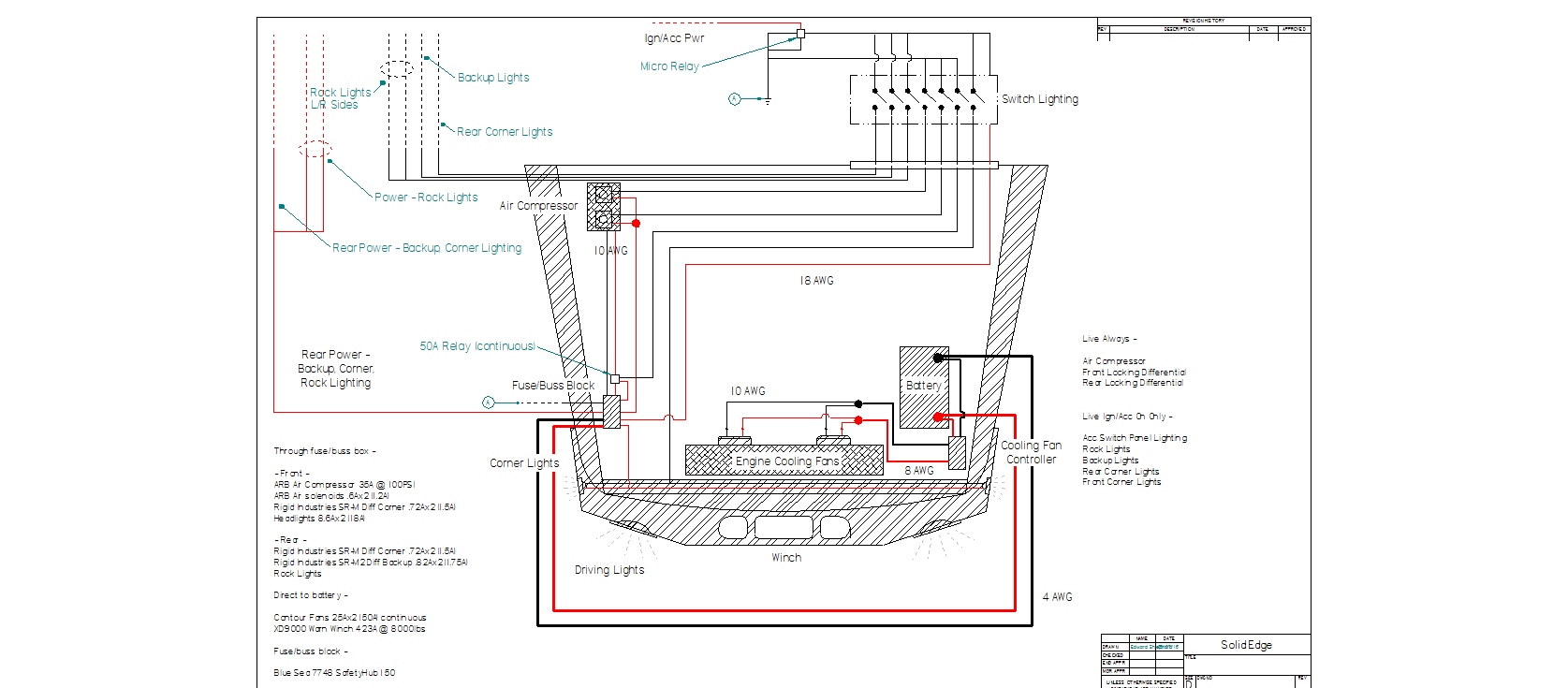 I don't want the lighting to work unless the key is turned on so I added a micro relay that will go in the accessory switch panel that will sit where the OEM single CD player normally sits. I DO want the compressor and locking differentials to work irrespective of whether the key is on or not. The new ARB compressor pulls a lot more amperage than my original QuickAir I. The lockers work at about 90-100 psi and for only the lockers, a smaller relay would work fine, but if the compressor is used for airing up tires I want a relay that's rated for continuous duty at at least 40A but better @ 50A. Too many relays are over-rated so some slop here is good. I haven't decided if I'm going to run my panel/switch grounds all the way back to the fuss/buss block or ground to the body. Either will work, but one/two grounds back to the negative buss on the block would be more reliable long term. At most it looks like 8A total through the firewall so one or two more wires won't hurt anything. (see A) Try as I could this weekend, I couldn't find anything in the way of switch panels that will fit where the single CD player sits. I'm not even sure I can fit 7 of the rocker style labeled switches in that space. I'm also not sure using unprotected switches there is a good idea.  If one of the lights are accidentally turned on by something sliding around in the cab or an inadvertent finger jab on a bump, its probably not a big deal. Having one (or both) of the lockers accidentally turned on or off or some combination thereof at the wrong time on the wrong terrain could be terminal. Wouldn't be the first time something sliding around in the front of the cab landed there on a really steep decent. I'm not even sure that's where I want the locker switches - that's an awful long reach for those. Have to think about this some more. I looked for more fuse/buss blocks this weekend, but the Blue Sea is still the best I could find for this use. I could put together my own but it'd take up three times the space. Edward |
|
|
|
Post by ES_97Sport on Sept 21, 2016 19:44:21 GMT -5
Updated diagram: 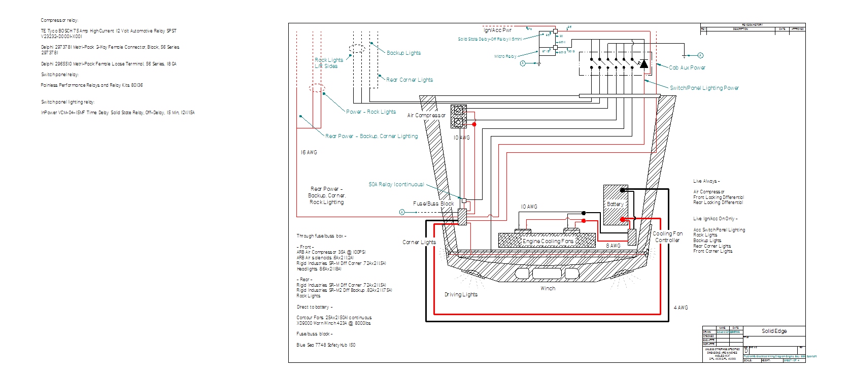 Changes: I merged the rear corner and backup lights into one switch. The reasoning was that if I needed one, I probably would need both. AND I can't fit 7 switches in the space I have so one had to go.  I still have to redraw the panel to see if 6 actually works .... I wanted the panel lighting to shut off when the vehicle is off. Kinda goes without saying. BUT, I DIDN'T want it to turn off immediately as the compressor and locker solenoids might be in use (those are 24/7 active). That got me to thinking ... it would be nice, if one or more of the switches were on, NONE of the lighting (rock lights, corner/BU lights) turned off immediately when the vehicle was shut off. So, using a delay-off relay relay and a micro relay, the panel lighting as well as any exterior lighting that is turned on on the panel will stay on for 15 minutes after the ignition is turned off. Edward |
|
|
|
Post by ES_97Sport on Sept 22, 2016 17:33:35 GMT -5
Updated diagram: 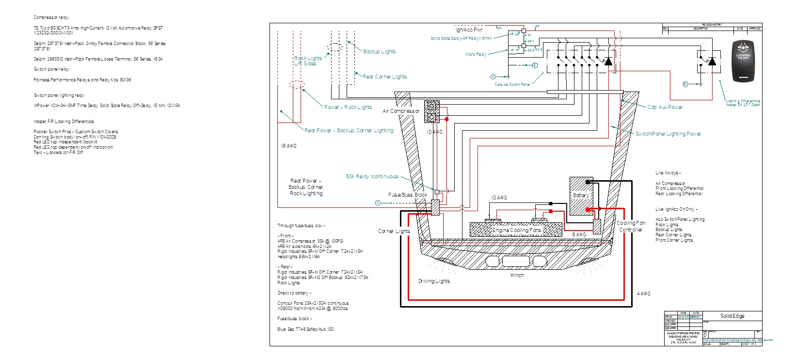 Changes: Having the F/R locking differential switches on the console is not a workable solution. There are several reasons that make this just an overall bad idea. However, there also isn't room on the dash for a bunch of switches. In the process of working this through my head last night, I remembered that the OEM L/D switch next to the driving light switch will go away when the axles are installed with ARBs so it frees up space for a Carling switch as I have in the big Sport in that location. That got me thinking about what happens when I'm 'wheeling - what would be sufficient is an easily accessible 'on/off' switch just to activate/deactivate the lockers. If I inserted a third switch (in reach on the dash) into the solenoid circuits, I could set the Front and Rear lockers however I wanted from the console and turn both on/off with the control switch on the dash. That's going to sound hokey to a lot of people that wheel, but reality is I either need both lockers or none about 99.9998% of the time. Also its a similarly rare percentage of the time that I need to lock or unlock A differential in the middle of an obstacle. For the vast majority of the time, I see both lockers activated at the console panel and using the dash switch to control on/off - exactly how my big black Sport works now. This configuration - unlike the big Sport - allows me to change the configuration around and activate/deactivate the F/R independently of each other. I found a company that does custom Carling switch covers so I could create a 'master' locking differentials cover. Having a cover on the switch that says 'Front' when it locks both is somewhat confusing to people unfamiliar with the vehicle and not particularly safe. To-Do: Front cornering light wiring design, wire gauges, and the physical console panel design. Edward |
|
|
|
Post by ES_97Sport on Sept 23, 2016 19:54:09 GMT -5
Accessory Switch Panel: 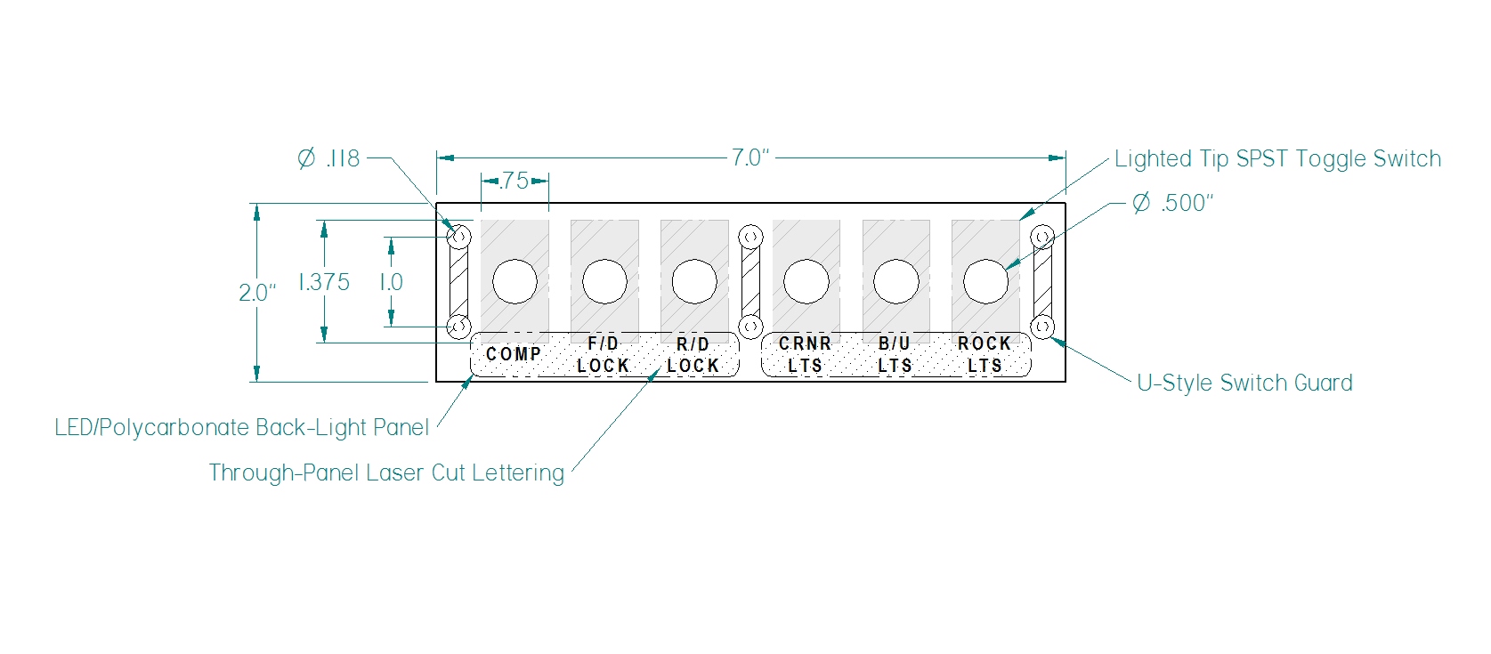 Front view of the accessories switch panel that will fit where the OEM single CD player normally sits in the front of the console. The entire thing will be cut on a laser table (including the lettering) and then powder coated. LED 'edge lighting' will be used to illuminate the lettering from behind. Suitable polycarbonate or whatever with four 130 degree very small, white LEDs. Sea Dog tip-lighted toggle switches - white off/red on. Besides being a good switch, its one of the few that don't go overboard on the lighting. Illuminated but not blinding. I couldn't fit a U switch protector on each side of every switch. I had to settle for three. I did choose stainless rather than aluminum. The studs are M3 - not the most durable size if made out of aluminum. I also found boots that may or may not work to seal the toggle switch levers. I'm going to try them and see. It'd be nice to keep the dust out but also to cover up the switch attaching nut/washer. The entire panel will be cut in one piece and then bent to hold the switches, protectors, relays and the harness connector. This way the entire thing will come out and install as a unit, just like the original OEM CD, so if a dealership tech has to get into the console it won't be any harder to remove than the CD player. I have my big Sport back for the weekend so I'm going to get into the console and take measurements four mounting and depth and then it'll be time to work out the entire CAD diagram. I haven't decided what to powder coat the panel in. Maybe a 80% black or possibly black fine crinkle .... Note: The dotted background under the letting and the dashed line around the dots is where the lighting panels will go INSIDE the panel; they will not be visible on the outside. Edward |
|
|
|
Post by ES_97Sport on Sept 26, 2016 14:53:26 GMT -5
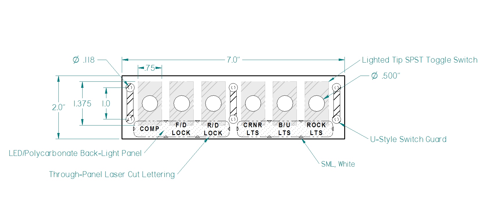 Changes: Added the LEDs for the edge lighting of the two panels behind the lettering. I'll adjust the intensity of the LEDs when I do the back-light mockup. Moved the lettering up slightly. I may move it up slightly more when I get the complete panel layout done, but it won't be a noticeable difference. Edward |
|
|
|
Post by dirk on Sept 26, 2016 19:04:54 GMT -5
Coming along, glad you don't just rush into things, and think them out b4 execution. And share with us for additional ideas for us.
|
|
|
|
Post by ES_97Sport on Sept 26, 2016 20:03:23 GMT -5
Preliminary front cornering lights: 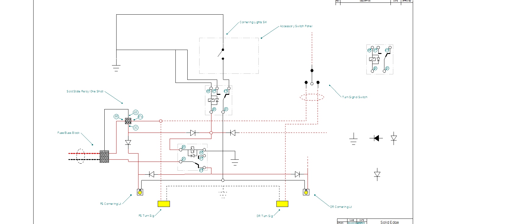 Cornering Light Breakout: I wanted to get something on 'paper' for the cornering lights as that's the last piece left unfinished on the main diagram. This diagram incorporates what we'd discussed earlier in the thread - both automatic lights that come on when their respective turn signal is switched on, and the ability to manually turn both lamps on/off via an accessory switch in the cab. Rather than use the rough but functional capacitor method above, I incorporated a solid state relay that accomplishes the same thing. Again, the downside is the ridiculous cost of the required 2 relays. To get the turn signals to 'override' the accessory switch, two standard 5 connection micro relays are triggered by the solid state relay when the turn signal is turned on for either side. The nice thing is no matter what position the accessory switch is in, the associated turn lamp's corner light will come on. The maybe not so nice thing is there is no way to completely disable the cornering lights. I don't really have a problem with that, so .... The diagram only shows the passenger side. The driver side is just a mirror so I didn't bother drawing up both for the time being. I need to print this out and incorporate it into the main diagram once I've cleaned it up. Edward |
|
|
|
Post by ES_97Sport on Sept 26, 2016 20:17:14 GMT -5
Coming along, glad you don't just rush into things, and think them out b4 execution. And share with us for additional ideas for us. Thanks! Slowly. I hate dealing with electrical so I absolutely want this to work the first time. I also don't want to make this project any more expensive than it is already going to be. AND I don't have time to re-do all this three times before I get it the way I want it.  All that and I promised the techs that this one wouldn't be the rats nest of electrical wiring that my big Sport is. If this all works correctly, after the '99 is done, I'll rip out all the wiring on the '97 and re-do it like this. I will. If anyone has any ideas or suggestions, I'd appreciate it if they'd share as well. Edward |
|
|
|
Post by ES_97Sport on Sept 27, 2016 22:12:18 GMT -5
Updated diagram: 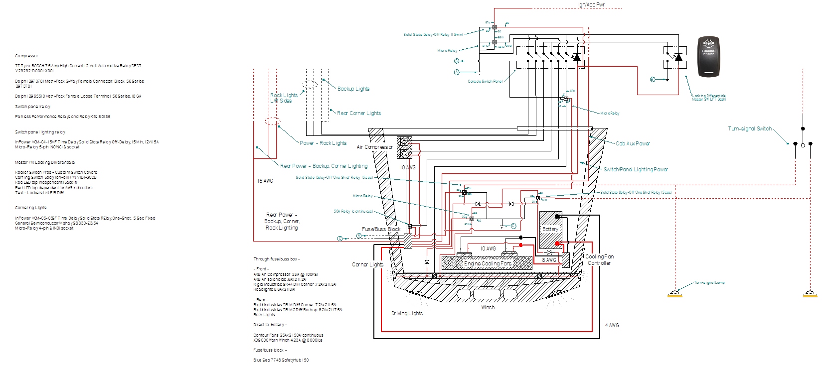 Changes: Added in the circuitry for the front cornering lights. Edward |
|
|
|
Post by ES_97Sport on Sept 28, 2016 18:18:30 GMT -5
Updated diagram: Cornering Lights 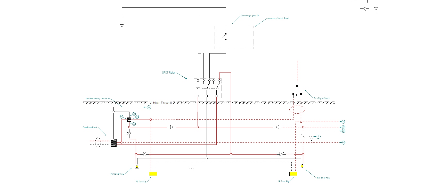 Changes: The more I looked at this, the less I liked it. Several things ... Up to this point, I have four (4) relays located within the engine bay. Two solid state relays, the 50A relay for the compressor and one of the two relays for the front cornering lights. The compressor relay and solid state relays really need to live where they are. But, I HATE having non-weatherproof relays living outside the cab. I haven't had much luck finding weather-tight micro-relays and I flat refuse to waste my 40A standard weather-tight relays on 1-2A circuits. And they're HUGE in comparison and I have limited space to work with. Every time I looked at the diagram and thought about wiring it I got a little nauseous. The only reason to run two relays was to keep from running two more wires through the firewall. At last count I was up to 9 wires and I decided last week that I would use one of the two DIY bulkhead connectors I already have so 2 wires more or less wouldn't make any difference. The DIY connector will accommodate 22 connections. DIY Auto Tune - Weather Pack 22 Position Bulkhead Connector KitSo, I said screw it, I'm going to redraw this with a DPDT relay and see what I end up with. Much better. Unfortunately, this means I'll have three relays mounted in the accessory switch enclosure so I need to enlarge the enclosure slightly, and it'll use an extra 20' of 18AWG, but at the ridiculous amounts they charge for micro-relays, eliminating that one relays already pays for the changes several times over. And I have one less relay at the mercy of the elements. Now I have to redraw the main diagram .... Edward |
|
|
|
Post by ES_97Sport on Oct 4, 2016 22:06:12 GMT -5
Updated diagram: 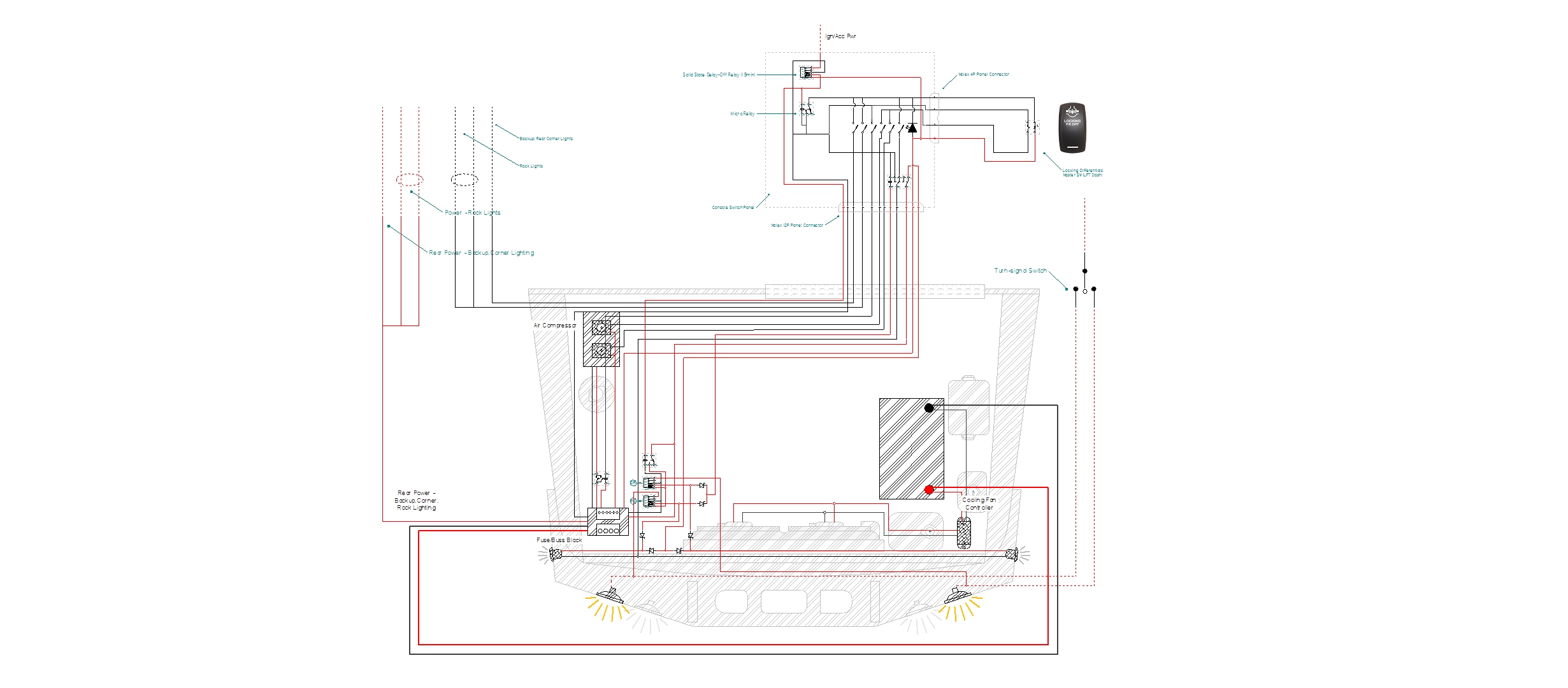 Changes: Redraw of the entire diagram - easier than trying to clean up the original. Redrew relay and switch symbols with appropriate pin-out notes. All except the Solid State relays are Bosch/TE. Closer to having all the appropriate wire gauges noted. Added Molex panel connectors so the harness can be plugged and unplugged from the Accessory Switch Panel. The individual terminals in a connector are rated at 5A. More than enough for this application. I got the entire front cornering light setup drawn and realized that the solid state cornering relays would be on 24/7 forever. Even though that's how the SS relay in the Accessory Switch Panel (inside the cab) works, I just wasn't crazy about having live-all-the-time SS microprocessor relays under the hood. I had one pin left on the panel connector so I ran a feed back from the internal SS relay to a micro relay that feeds power to the SS relays under the hood. When the ignition is turned on, the SS relay in the console will energize the micro-relay under the hood turning on power to the front cornering light system. To-Do: Work out the wire gauges for the rest of the wiring. Redraw the toggle switches into the diagram with their illumination circuits. Edward |
|
|
|
Post by ES_97Sport on Oct 7, 2016 19:23:46 GMT -5
Updated diagram: 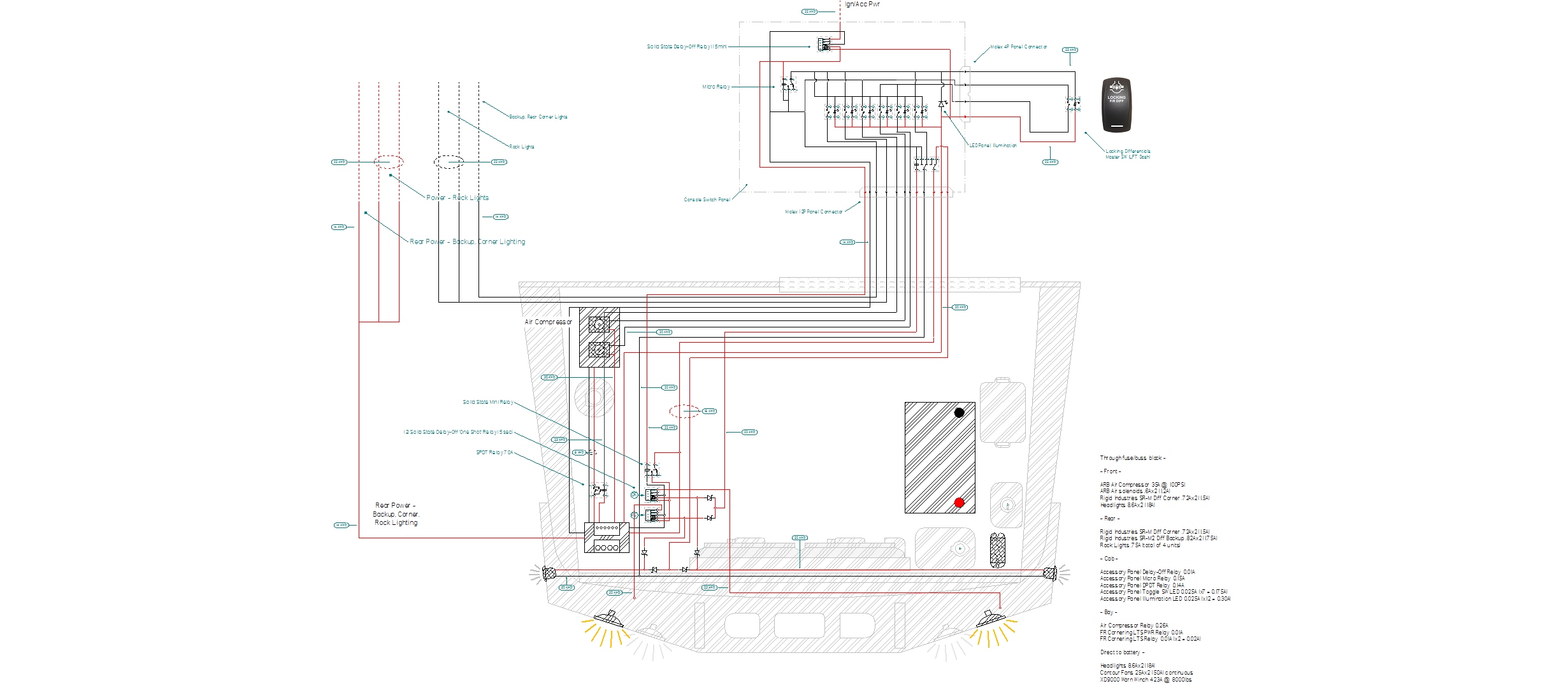 Changes: I went back through all the documentation and recalculated current draw and then mocked up the Sport dimensions to scale and figured out all the wiring gauges and added a generous fudge factor. I figured everything very conservatively. Modeled the toggle switches and added appropriate notations for pin-outs. I changed from the Molex .062" 12P connector to the .093" connector. After recalculating all the current draw, I figured out that the total on the ground pin would be around 8A with absolutely EVERYTHING on. Its unlikely that everything will be turned on at once for any length of time but I didn't want to rely on that. I changed the primary wiring for the compressor to 8AWG from 10AWG. The only reason I did this was in case I needed to use the compressor to fill tires where it would be running for an extended period of time. If I were just going to use it for the lockers, 12AWG would have been sufficient. Edward |
|
|
|
Post by ES_97Sport on Oct 10, 2016 22:33:08 GMT -5
Updated diagram: 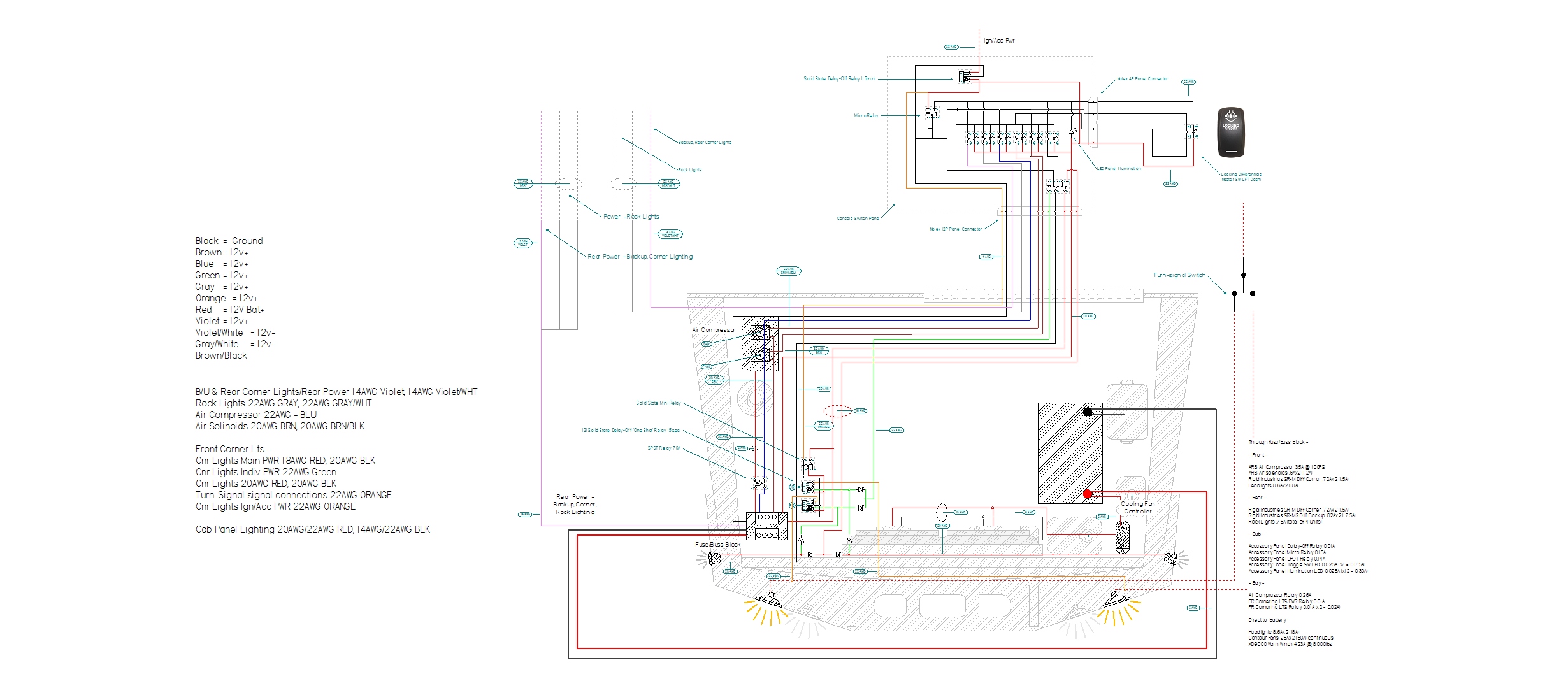 Changes: Added the wiring colors to the diagram. Changed the primary power feed from 4AWG to 2AWG. Maximum amperage as configured + headlights, with everything running at maximum draw is about 65A. Which is an unlikely scenario, but rather than one day find something else that draws 40A and have to pull the 4AWG - and since I have to order other cable from the same place - I figured I'd bump it up to 2AWG now rather than later. It will be a lot easier to do it now when the whole front is off rather than after there's a bunch of stuff in the way. Changed the primary power feed for the compressor to 8AWG from 10AWG. Same reasoning. Easier to do it that way now rather than latter. And I have to get the same 8AWG for the fans anyway, so .... Besides, I realized this weekend I was out of 10AWG. The diagram is complete. I will add some strategically placed connectors during the build when I know exactly where they'll need to go and what I'll need. Edward |
|
|
|
Post by ES_97Sport on Oct 17, 2016 19:18:06 GMT -5
Updated diagram: 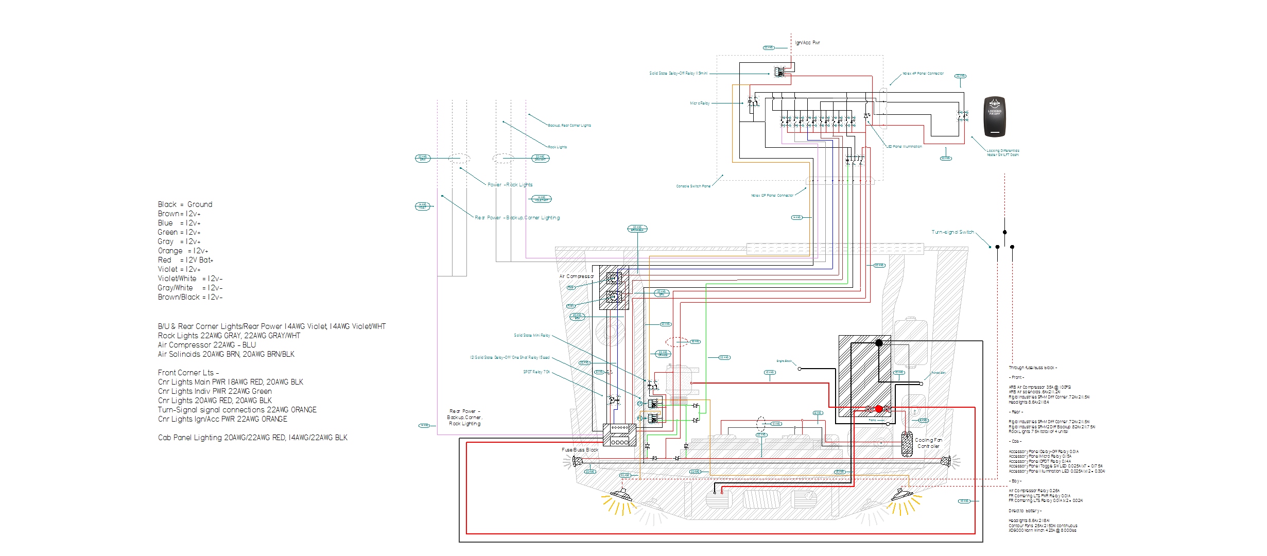 Electrical Wiring Diagram Engine Bay 1999 Montero Sport (PDF) Electrical Wiring Diagram Engine Bay 1999 Montero Sport (PDF)Changes: Added winch cable circuit. The OEM Warn cable is 2AWG; I'm substituting 1/0AWG. As far as I'm aware, the general consensus is 2/0, but unless something in my life drastically changes, all my pulls are short, few and far between. I've never had issues with the 2AWG on my big Sport but I've never been overjoyed with it either. Good thing to fix up front on this build. Added the OEM primary ground circuit to the diagram. For documentation purposes and also as its part of the following change ... Added the HO alternator auxiliary 12v+ circuit. Instead of running both a pos and neg lead from the alternator, I will run a 1/0AWG from the alternator for the 12v+ and upgrade the OEM 12v- ground cable to 1/0AWG. The alternator grounds though the case to the engine block and the OEM cable grounds to the engine block on the opposite side (with no insulators like gaskets in the middle). In this case and based on my experience, a separate 12v- cable is useless - PROVIDED - the OEM 12v- negative cable is sized appropriately. Technically, the 12v- can be a smaller gauge cable as its about 1/2 the length of the 12v+ cable and the other '1/2' of the 'length' is the engine block, but its easier to buy all the same gauge cable and lugs for everything rather than bits and pieces for half a dozen different sized cables. Notes: Everything smaller than 8AWG will be stranded PTFE wiring. Its expensive but the temperature rating is much higher - 400 degrees - than cheaper PVC - about half PTFE - wiring which means it will last longer in a blistering hot engine bay. Its also smaller in diameter which will be nice when bundling 12 wires in a harness. Four fuses on the 12v+ battery post - 2 150A fuses for the alternator and Blue Sea fuse/buss block respectively, a 500A for the winch and a 60A for the engine cooling fan controller. Terminal lug sizes: Winch Electrical Cables
1/0AWG
winch+ = 1 5/16" straight
winch- = 1 5/16" straight
battery+ = 1 5/16" straight
battery- = 1 5/16" straight
Negative Battery Cable
1/0AWG
block = 1 3/8" 90 degree
frame = 2 5/16" 45 degree (or straight, combination)
fender = 2 1/4" straight
battery- = 1 5/16" straight
Aux Alternator Cables
1/0AWG
alternator+ = 1 5/16" 90 degree
battery+ = 1 5/16" straight
Supplementary Fuse/Buss Block Cables
1/0AWG
fuse box+/- = 2 5/16" straight
battery+ = 1 5/16" straight
battery- = 1 5/16" straightEdward |
|
|
|
Post by ES_97Sport on Oct 28, 2016 20:27:59 GMT -5
Accessory switch enclosure: 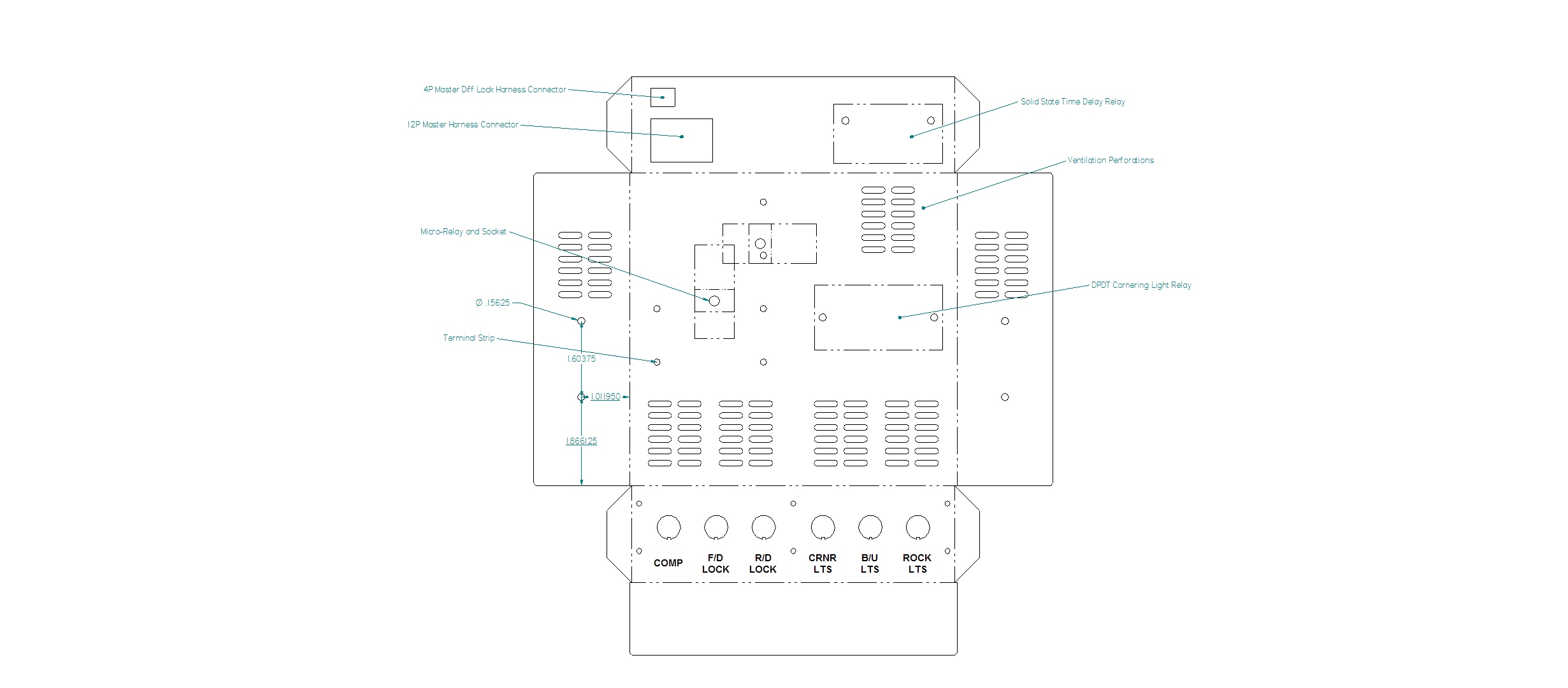 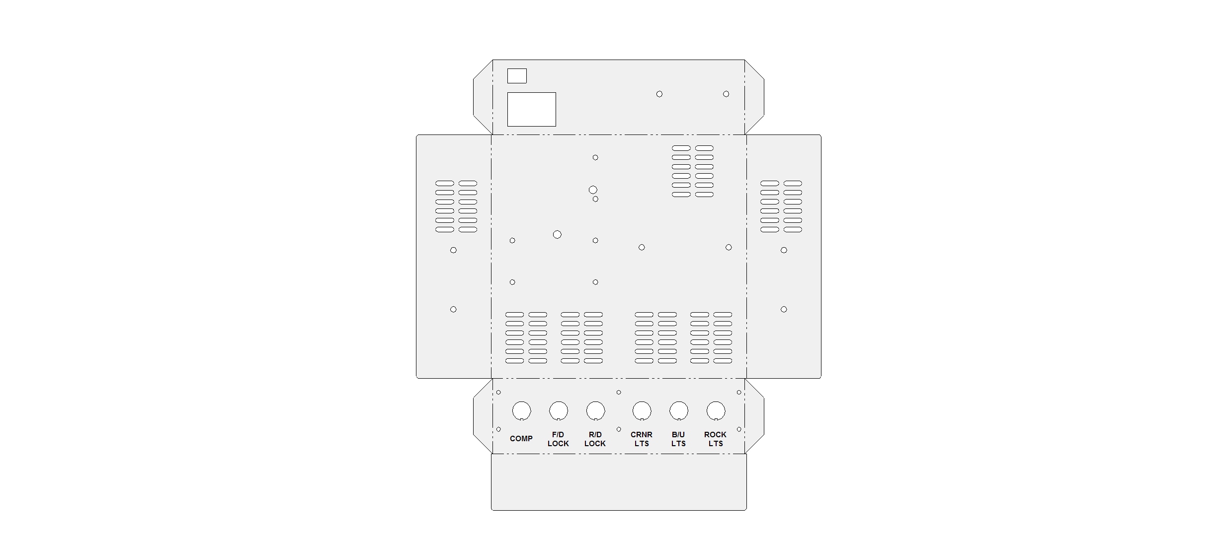 The dotted lines in the second picture are the folds. Those familiar with the single CD player in the console will probably recognize the basic layout as I basically copied the dimensions of the enclosure. The dotted blocks in the first pic are the areas used by the components. Edward |
|


 If one of the lights are accidentally turned on by something sliding around in the cab or an inadvertent finger jab on a bump, its probably not a big deal. Having one (or both) of the lockers accidentally turned on or off or some combination thereof at the wrong time on the wrong terrain could be terminal.
  I still have to redraw the panel to see if 6 actually works ....
