How to replace Rotors/Calipers/Wheel bearings
Dec 9, 2011 13:21:08 GMT -5
mrgalantguy, fikse, and 1 more like this
Post by Monter02 on Dec 9, 2011 13:21:08 GMT -5
How to replace the rotors, calipers and wheel bearings on a 2002 Montero Sport XLS:
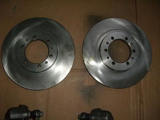
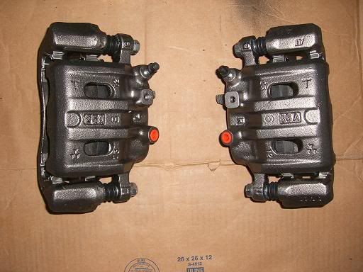
**One quick note here…I have a set of aftermarket 16” wheels that did not clear the old calipers, so I had to grind them down to fit. Rather than grinding down a new set of calipers, I decided to replace the rotors and calipers with a new set from a 15” wheel setup. All of the bolt holes line up, so it’s a straight swap, but you may notice that the rotor is smaller in the after setup than the before. This information should be appropriate for a simple replacement as well. You could also upgrade from the 15” setup to a 16” setup if you had bigger wheels, but you would probably have to replace the brake dust shield if going to a larger setup.
1.) First jack up the front end of your Montero Sport and support the SUV with jack stands. Next, remove the front wheels. Use a good penetrating catalyst like PB Blaster or WD-40 on all bolts. If you have a lot of corrosion, you may want to let it work for 24 hours or more. I have found PB Blaster to be one of the best penetrating sprays around.
When removing items, place them on a clean surface in the order that you removed them. I strongly advise taking pictures of all projects as you go along, so you can refer back to them if you forget the order.
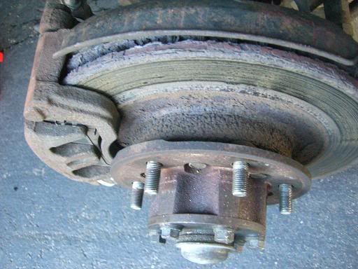
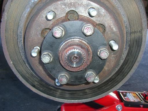
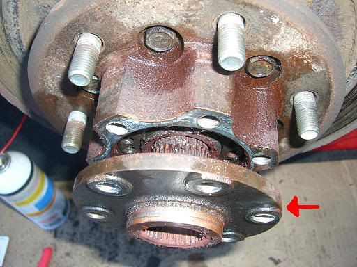
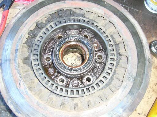
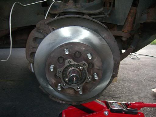
This is where I started. 10 years of New England weather and salt led to this corrosion:


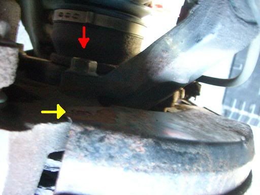
2.) Remove the two screws (yellow arrow) holding the brake dust shield in place, and loosen the two bolts (red arrow) holding the brake caliper to the disk brake spindle.
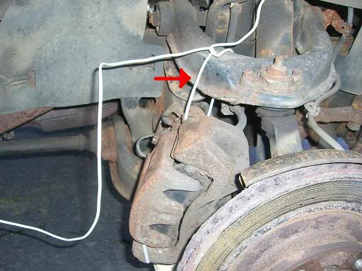
3.) Support the caliper by using wrapping a coat hanger or heavy gauge wire around the caliper and securing it to the upper control arm
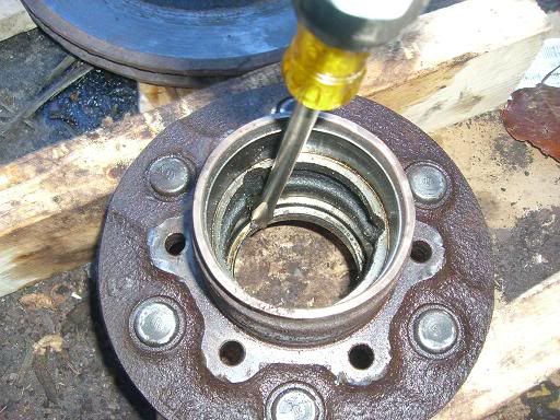
4.) Remove the dust cap by placing a large flat tip screw driver behind the cap and popping forward
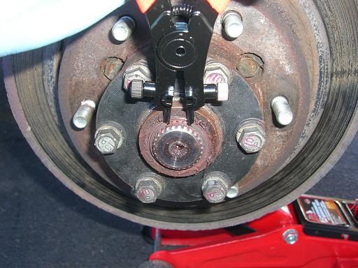
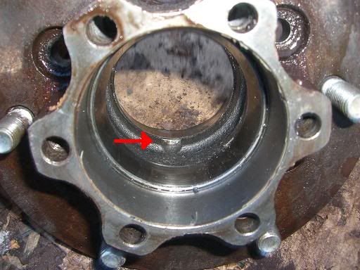
5.) Use a set of snap wring pliers to open the snap wring and pry it out of the groove it sits in.
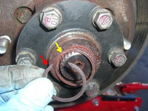
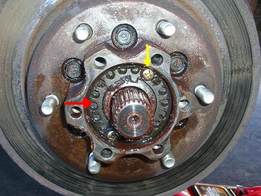
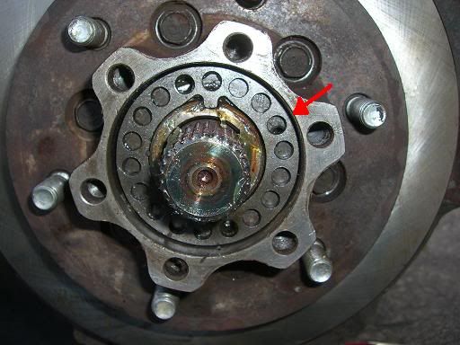
6.) The snap wring (red arrow) and shims (yellow arrow) will come loose.
7.) Next remove the 6 bolts (red arrow) holding the drive flange in place.
8.) Remove the drive flange (red arrow) by pulling outwards.
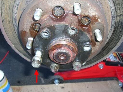
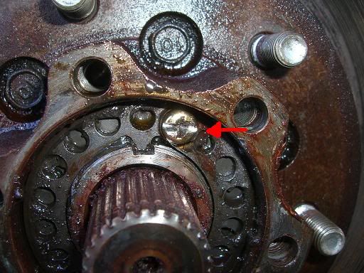
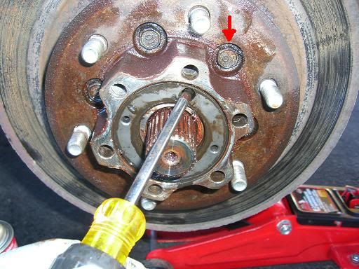
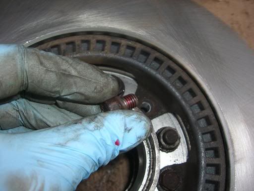
9.) You are now looking at the spring washer (red arrow) and the two brass screws (yellow arrow) that are bound to strip with a Phillips head screw driver.
10.) If the brass screws start to strip, which they will, cut a groove (red arrow) with a Dremel so you can remove them with a large slotted screw driver.
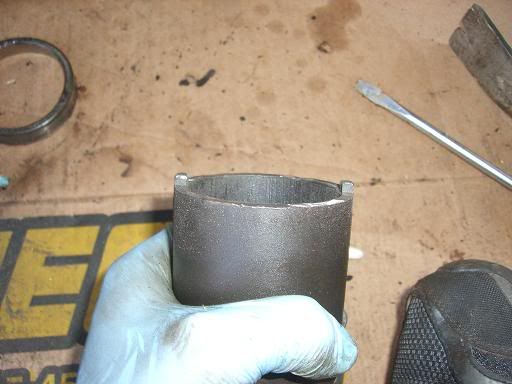
11.) You may or may not need the lock nut removal tool at this point. If you can not find one for a Montero Sport, find one for a 4WD ¾ ton GMC or Ford.

12.) And remove 4 of the nubs. The Montero Sport has two opposing nubs, but you can simply grind off the ones you don’t need.
13.) Remove the lock nut. Once the lock nut is loose, I found it easier to use a screw driver to spin the lock nut off.
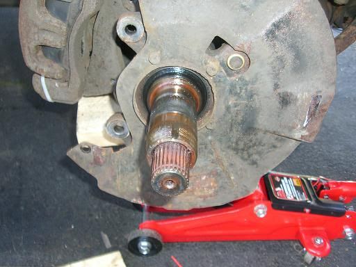
14.) The brake disk and hub are now free. Pull outward on the rotor and hub assembly and they will come off as one unit. You will be left with this. A brake dust shield with the spindle poking through.
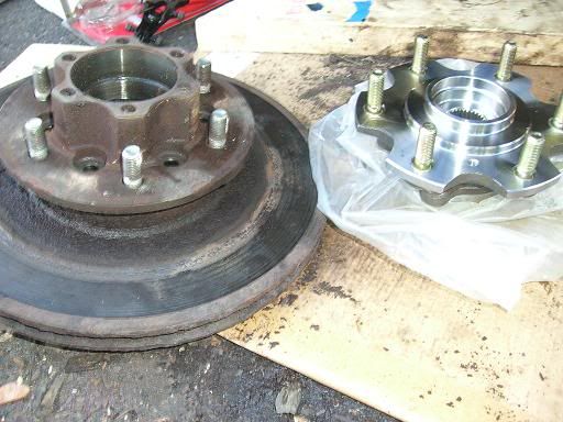
I was worried that the rotor and hub would have fused together with corrosion, so I purchased new hubs from Drive Tech America. However, the hubs they have listed for a Montero Sport, are actually for a Montero and are utterly useless in this application.
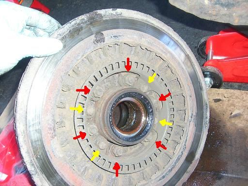
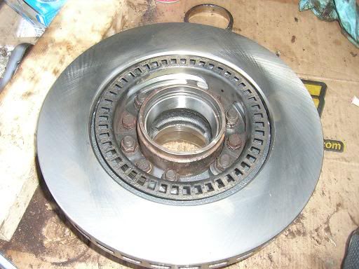
15.) Remove the 6 bolts (red arrow) holding the hub to the brake disc. And remove the 4 bolts (yellow arrow) holding the rotor to the brake disc. (note: I have always referred to the rotor and the disc as the same thing, but in this application Mitsubishi refers to them as two separate parts).
16.) Separate the rotor (red arrow) from the disc.
17.) As I feared, the hub and disc did not want to come apart. There is nothing left holding these parts together other than rust and grime. I used a thin pry bar and hammered it between the hub and disc, rotating the pry bar every few whacks.
18.) After I could see a little separation, I switched to a thicker pry bar. Eventually they popped apart.
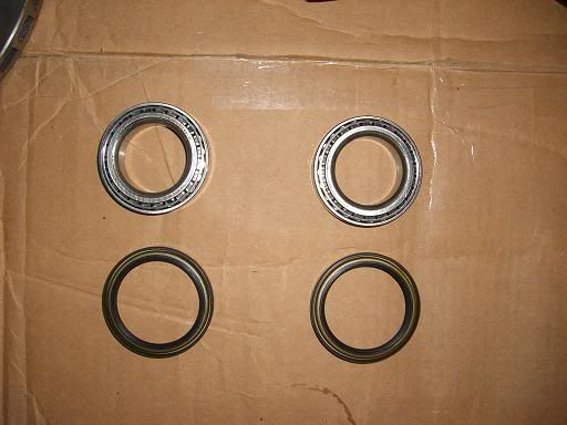
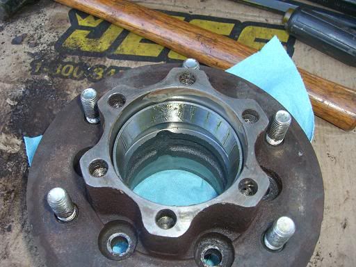
19.) If you are replacing the bearings, which you should if you are this far along. Pop out the old oil seal and remove the inner and out bearings. They will slide out easily. You will need to knock the bearing races out using a drift and a hammer. I didn’t have a drift, so I used a large slotted screw driver and a hammer. Just be sure not to gouge the hub. There are 3 reliefs (red arrow) by each race where you can place the tool.
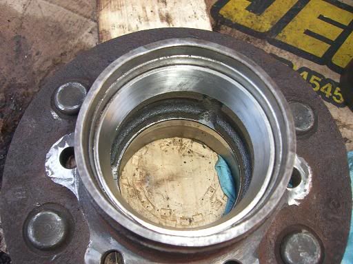
20.) Seat the new races using the proper size driver. I did not have a driver, so I flipped an old race upside down and used a rubber mallet and a block of wood to seat them most of the way in. Then I used the lock nut removal tool with a cloth towel wrapped around it, and the rubber mallet and block of wood to seat it the rest of the way in.
Now begins reassembly. Simply reverse the order of removal.
21.) Install the 6 bolts holding the rotor to the disc and torque to 36-43 ft-lbs. Install the 4 bolts holding the rotor to the disc and torque to 16 ft-lbs. I used red loc-tite on all of my bolts.
22.) Pack the bearings using a quality bearing grease. Insert the bearings into the races, and install new oil seal over the inner wheel bearing. Re-install rotor and hub assembly onto the spindle. Install the lock nut onto the spindle and hand tighten.
23.) Using the lock nut removal tool, torque the lock nut down to 94-145 ft-lbs, then back off to 0 ft-lbs, then re-torque to 18 ft-lbs.

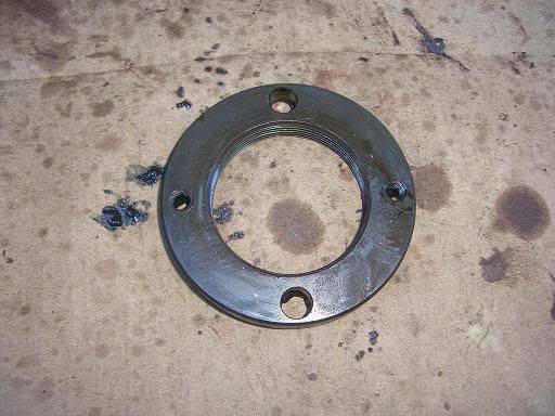
24.) Install the spring washer. If the screw holes in the spring washer (red arrow) and the screw holes in the lock nut don’t line up, you will need to remove the spring washer and back the lock nut off by as much as 30 degrees to line up the screw holes.
25.) Re-install the brass screws.
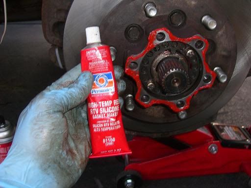
26.) Using High Temp Red RTV Silicone, or equivalent, make a bead around the perimeter of the hub to create a seal with the drive flange.
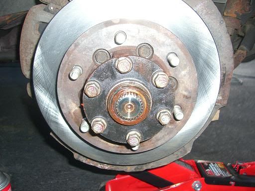
27.) Re-install the drive flange and torque the 6 bolts to 36-43 ft-lbs or torque.
28.) Re-install the shims and spring washer. Apply a bead of High Temp Red RTV Silicone, or equivalent, to the inside of the dust cap and re-install the dust cap.
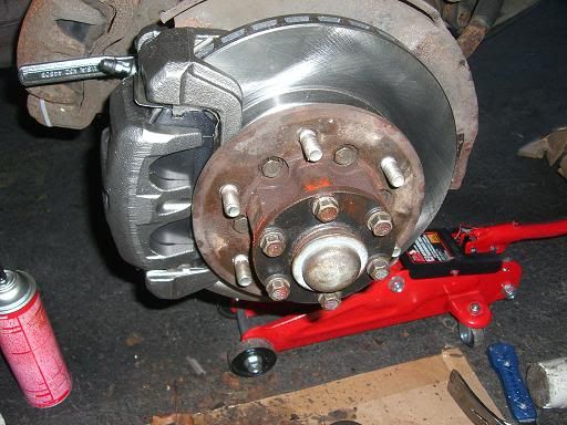
29a.) If you are not installing new calipers, simply reinstall the old calipers, apply red loc-tie to the bolts and torque the bolts to 65 ft-lbs.
29b.) If you are installing new calipers, remove the the two bolts holding the brake hose bracket to the caliper and then remove the brake hose from the old caliper. Screw the old hose onto the new caliper and attach the old bracket to the new caliper with the two bolts. It will be necessary to bleed the brakes once you have detached the brake hose as air will enter the line.
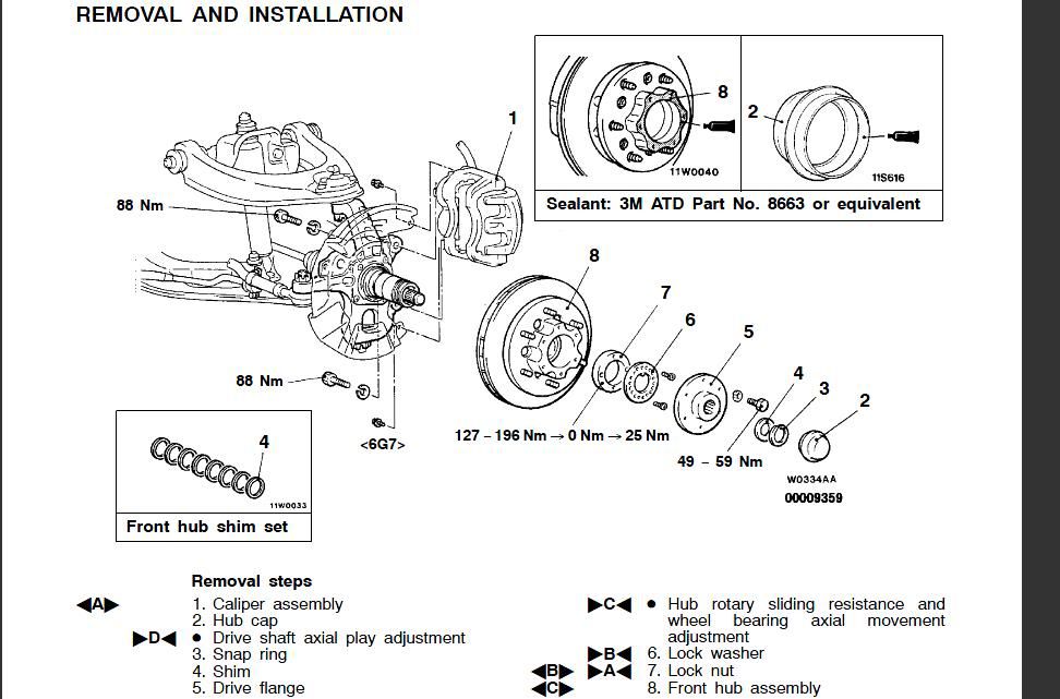
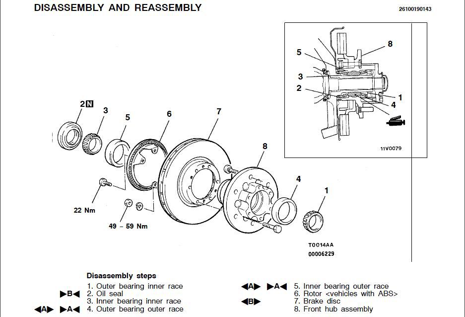
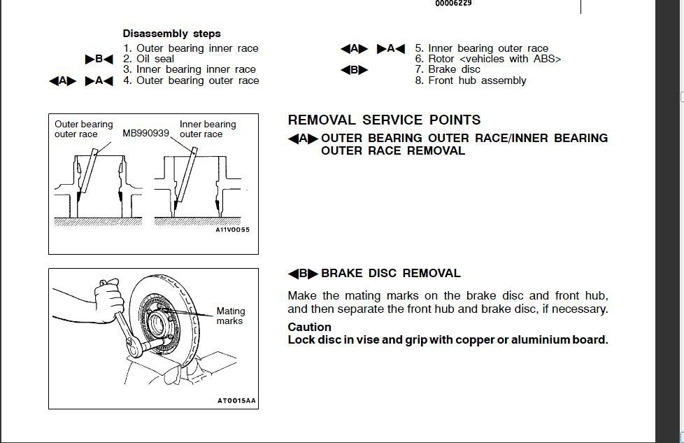
Useful Diagrams:
**One quick note here…I have a set of aftermarket 16” wheels that did not clear the old calipers, so I had to grind them down to fit. Rather than grinding down a new set of calipers, I decided to replace the rotors and calipers with a new set from a 15” wheel setup. All of the bolt holes line up, so it’s a straight swap, but you may notice that the rotor is smaller in the after setup than the before. This information should be appropriate for a simple replacement as well. You could also upgrade from the 15” setup to a 16” setup if you had bigger wheels, but you would probably have to replace the brake dust shield if going to a larger setup.
1.) First jack up the front end of your Montero Sport and support the SUV with jack stands. Next, remove the front wheels. Use a good penetrating catalyst like PB Blaster or WD-40 on all bolts. If you have a lot of corrosion, you may want to let it work for 24 hours or more. I have found PB Blaster to be one of the best penetrating sprays around.
When removing items, place them on a clean surface in the order that you removed them. I strongly advise taking pictures of all projects as you go along, so you can refer back to them if you forget the order.
This is where I started. 10 years of New England weather and salt led to this corrosion:
2.) Remove the two screws (yellow arrow) holding the brake dust shield in place, and loosen the two bolts (red arrow) holding the brake caliper to the disk brake spindle.
3.) Support the caliper by using wrapping a coat hanger or heavy gauge wire around the caliper and securing it to the upper control arm
4.) Remove the dust cap by placing a large flat tip screw driver behind the cap and popping forward
5.) Use a set of snap wring pliers to open the snap wring and pry it out of the groove it sits in.
6.) The snap wring (red arrow) and shims (yellow arrow) will come loose.
7.) Next remove the 6 bolts (red arrow) holding the drive flange in place.
8.) Remove the drive flange (red arrow) by pulling outwards.
9.) You are now looking at the spring washer (red arrow) and the two brass screws (yellow arrow) that are bound to strip with a Phillips head screw driver.
10.) If the brass screws start to strip, which they will, cut a groove (red arrow) with a Dremel so you can remove them with a large slotted screw driver.
11.) You may or may not need the lock nut removal tool at this point. If you can not find one for a Montero Sport, find one for a 4WD ¾ ton GMC or Ford.
12.) And remove 4 of the nubs. The Montero Sport has two opposing nubs, but you can simply grind off the ones you don’t need.
13.) Remove the lock nut. Once the lock nut is loose, I found it easier to use a screw driver to spin the lock nut off.
14.) The brake disk and hub are now free. Pull outward on the rotor and hub assembly and they will come off as one unit. You will be left with this. A brake dust shield with the spindle poking through.
I was worried that the rotor and hub would have fused together with corrosion, so I purchased new hubs from Drive Tech America. However, the hubs they have listed for a Montero Sport, are actually for a Montero and are utterly useless in this application.
15.) Remove the 6 bolts (red arrow) holding the hub to the brake disc. And remove the 4 bolts (yellow arrow) holding the rotor to the brake disc. (note: I have always referred to the rotor and the disc as the same thing, but in this application Mitsubishi refers to them as two separate parts).
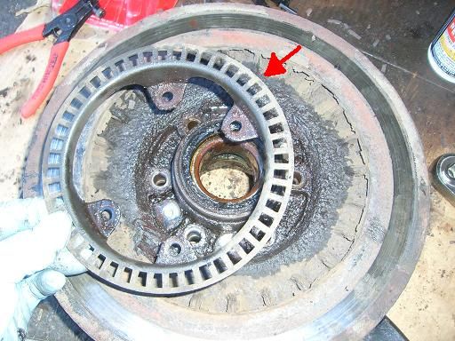
16.) Separate the rotor (red arrow) from the disc.
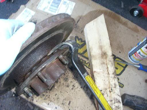
17.) As I feared, the hub and disc did not want to come apart. There is nothing left holding these parts together other than rust and grime. I used a thin pry bar and hammered it between the hub and disc, rotating the pry bar every few whacks.
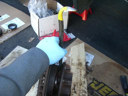
18.) After I could see a little separation, I switched to a thicker pry bar. Eventually they popped apart.
19.) If you are replacing the bearings, which you should if you are this far along. Pop out the old oil seal and remove the inner and out bearings. They will slide out easily. You will need to knock the bearing races out using a drift and a hammer. I didn’t have a drift, so I used a large slotted screw driver and a hammer. Just be sure not to gouge the hub. There are 3 reliefs (red arrow) by each race where you can place the tool.
20.) Seat the new races using the proper size driver. I did not have a driver, so I flipped an old race upside down and used a rubber mallet and a block of wood to seat them most of the way in. Then I used the lock nut removal tool with a cloth towel wrapped around it, and the rubber mallet and block of wood to seat it the rest of the way in.
Now begins reassembly. Simply reverse the order of removal.
21.) Install the 6 bolts holding the rotor to the disc and torque to 36-43 ft-lbs. Install the 4 bolts holding the rotor to the disc and torque to 16 ft-lbs. I used red loc-tite on all of my bolts.
22.) Pack the bearings using a quality bearing grease. Insert the bearings into the races, and install new oil seal over the inner wheel bearing. Re-install rotor and hub assembly onto the spindle. Install the lock nut onto the spindle and hand tighten.
23.) Using the lock nut removal tool, torque the lock nut down to 94-145 ft-lbs, then back off to 0 ft-lbs, then re-torque to 18 ft-lbs.
24.) Install the spring washer. If the screw holes in the spring washer (red arrow) and the screw holes in the lock nut don’t line up, you will need to remove the spring washer and back the lock nut off by as much as 30 degrees to line up the screw holes.
25.) Re-install the brass screws.
26.) Using High Temp Red RTV Silicone, or equivalent, make a bead around the perimeter of the hub to create a seal with the drive flange.
27.) Re-install the drive flange and torque the 6 bolts to 36-43 ft-lbs or torque.
28.) Re-install the shims and spring washer. Apply a bead of High Temp Red RTV Silicone, or equivalent, to the inside of the dust cap and re-install the dust cap.
29a.) If you are not installing new calipers, simply reinstall the old calipers, apply red loc-tie to the bolts and torque the bolts to 65 ft-lbs.
29b.) If you are installing new calipers, remove the the two bolts holding the brake hose bracket to the caliper and then remove the brake hose from the old caliper. Screw the old hose onto the new caliper and attach the old bracket to the new caliper with the two bolts. It will be necessary to bleed the brakes once you have detached the brake hose as air will enter the line.
Useful Diagrams:


 It is a LOT easier if you have a driver. Its also possible to install the races without a driver but the odds are close to 100% you'll screw up the race.