Derale 16795 PWM Fan Controler Installation
Aug 8, 2016 18:23:34 GMT -5
bdmontero and jpele21 like this
Post by ES_97Sport on Aug 8, 2016 18:23:34 GMT -5
This is a writeup on installing the Derale 16795 PWM Engine Cooling Fan controller with the Derale 16750 Replacement NPT Thread-In temperature sensor probe in a Gen 1 Montero Sport. The vehicle the Derale controller was installed in was previously running a SPAL PWM v3 controller with dual shrouded Ford Contour fans and a custom (very large) Griffon aluminum radiator.
On with it then ...
Listed below are all the parts and tools I used in the installation. Having previously done installations like this before, and having previously dealt with Derale's 'install kits', and after doing a lot of research on this particular kit, I had a fairly good idea what wouldn't work, what was garbage and what needed to be changed for my application.
Parts -
Tools -
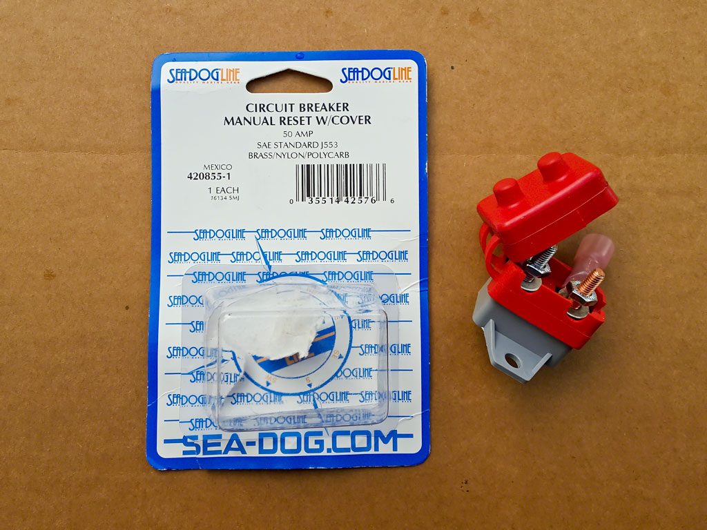
I should point out now why the parts list is so large. While the controller itself appears to be good quality, the installation kit is IMHO, cheap garbage. The 10 AWG wire doesn't appear to actually be 10 AWG. Its appears smaller (like 11 AWG if there were such a thing) and its very few, very thick strands - a hallmark of cheap electrical wiring. It was sufficient for a 10-12" run, but there is NO WAY I'd do an entire installation with that wire. The terminals are just cheap auto parts store grade crimp connectors and IMHO not up to carrying upwards of 30 AMPS - especially with eyelets that small. The resetting circuit breaker has NO protection. NO cover, NO terminal covers, nothing. SERIOUSLY?!
The Installation -
The Derale wiring directions are reasonably straight forward. It is clear, though, that while this controller will drive two Contour fans, the controller itself wasn't designed with dual fans in mind. The terminals are very close together - trying to run four 10 AWG wires to the controller isn't a good idea if its even possible, and four 8 AWG wires wouldn't be possible at all.
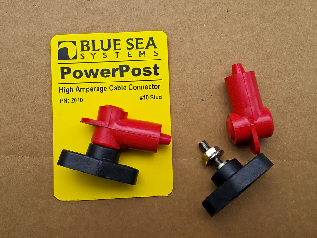
So, the first thing I did was patch some of the 10 AWG wire into the OEM plug harness with four ring terminals so that I could attach those wires to junction posts. (Blue Sea Systems Mini PowerPost) The 10 AWG was soldered to the OEM pig tails, sealed with shrink tubing and then the whole thing covered in a protective sheath. (Taylor Cable Red Thermal Protector Sleeving) The ring terminals came with heat shrink tubing with the glue inside to completely seal the connection.
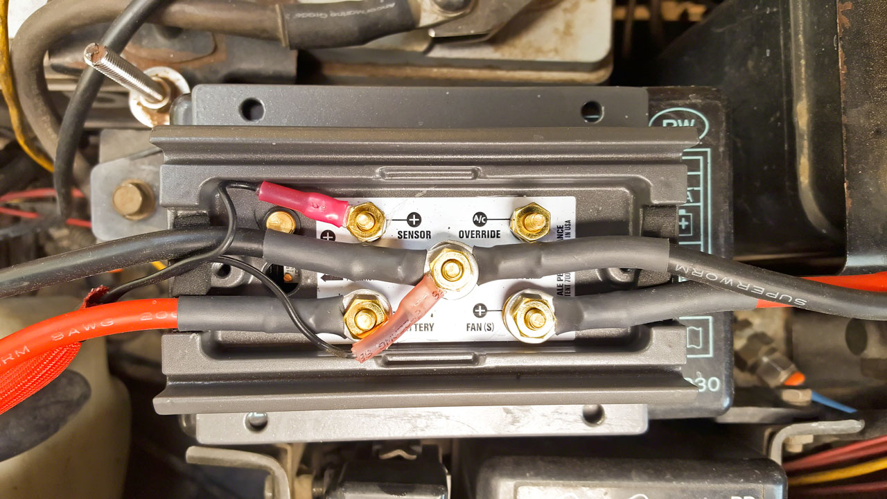
The controller has two positive (+) terminals and ONE negative (-) terminal, in a very small space. With a dual fan setup using 10 AWG from the fans, this would require 2 positive and 2 negative wires coming in one side of the controller. The two negative wires from the fans would go to the same post in the controller, which has a third running to the negative battery terminal AND another ring terminal for the sensor. This is FOUR terminals connecting to the same TINY post. Trying to get all those connectors in that small a space without ending up with an electrical short is problematic. Running the 10 AWG fans wires to two junction posts and then running two 8 AWG wires to the controller was very clean and minimized the number of ring terminals in the controller.
The next step was running the 8 AWG from the junction posts to the controller. Easy-peasy. Uh, no. Big mistake #1. All the ring terminals wouldn't fit in the controller. Or on the junction posts. I really like Ancor's marine grade terminals. Their tinned and use heavy duty heat shrink with the glue inside. Which, unfortunately, makes them bulky. Step #1 - heat up the heat shrink after making the crimp and cut the heat shrink off with a razor knife. Step #2 - dig through my box of thin wall heat shrink tubing and heat shrink the four ring terminals. Problem solved. The thin walled heat shrink was perfect - it insulated the terminals from each other in the controller and added minimal bulk so that the boots on the junction posts fit correctly and the cover on the Derale controller closed and sealed. Stupid mistake #2. I ordered #10 ring terminals instead of #8 ring terminals for the controller end of the 8 AWG wires. Thankfully there's a VERY small difference between #8 and #10 so I could use the 8 AWG #10 terminals. Really stupid mistake #3. I forgot to put the wire sheath on BEFORE putting on all the ring terminals. It took 30 minutes but I finally, BARELY, managed to get both wires into the sheath. It sucked. A lot.
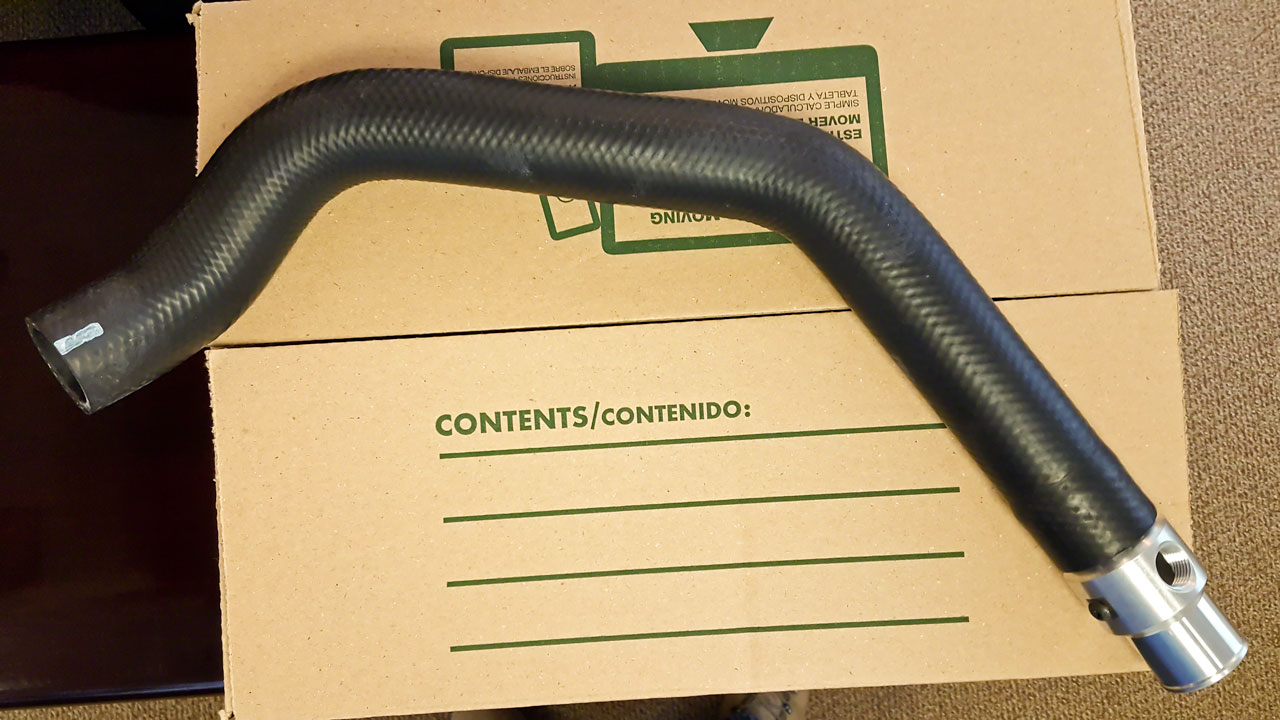
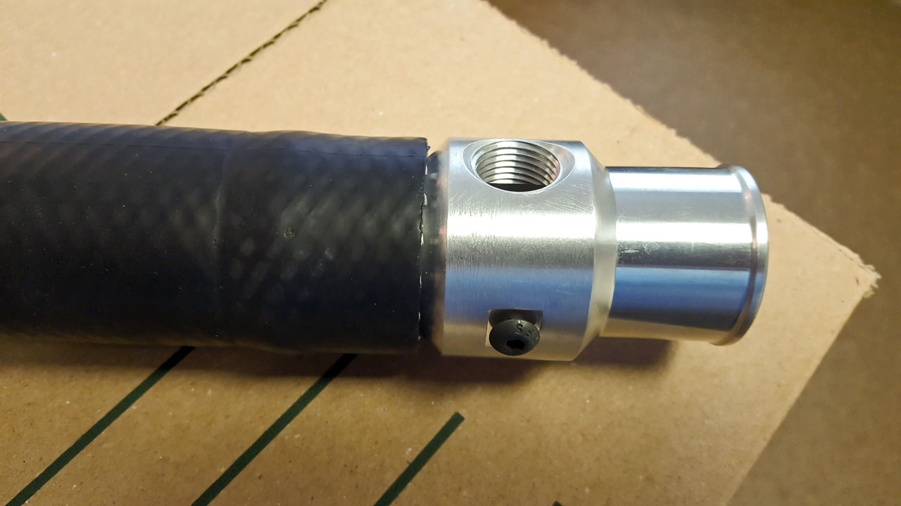
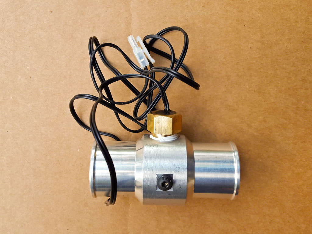
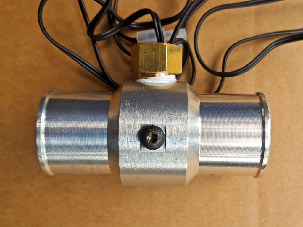
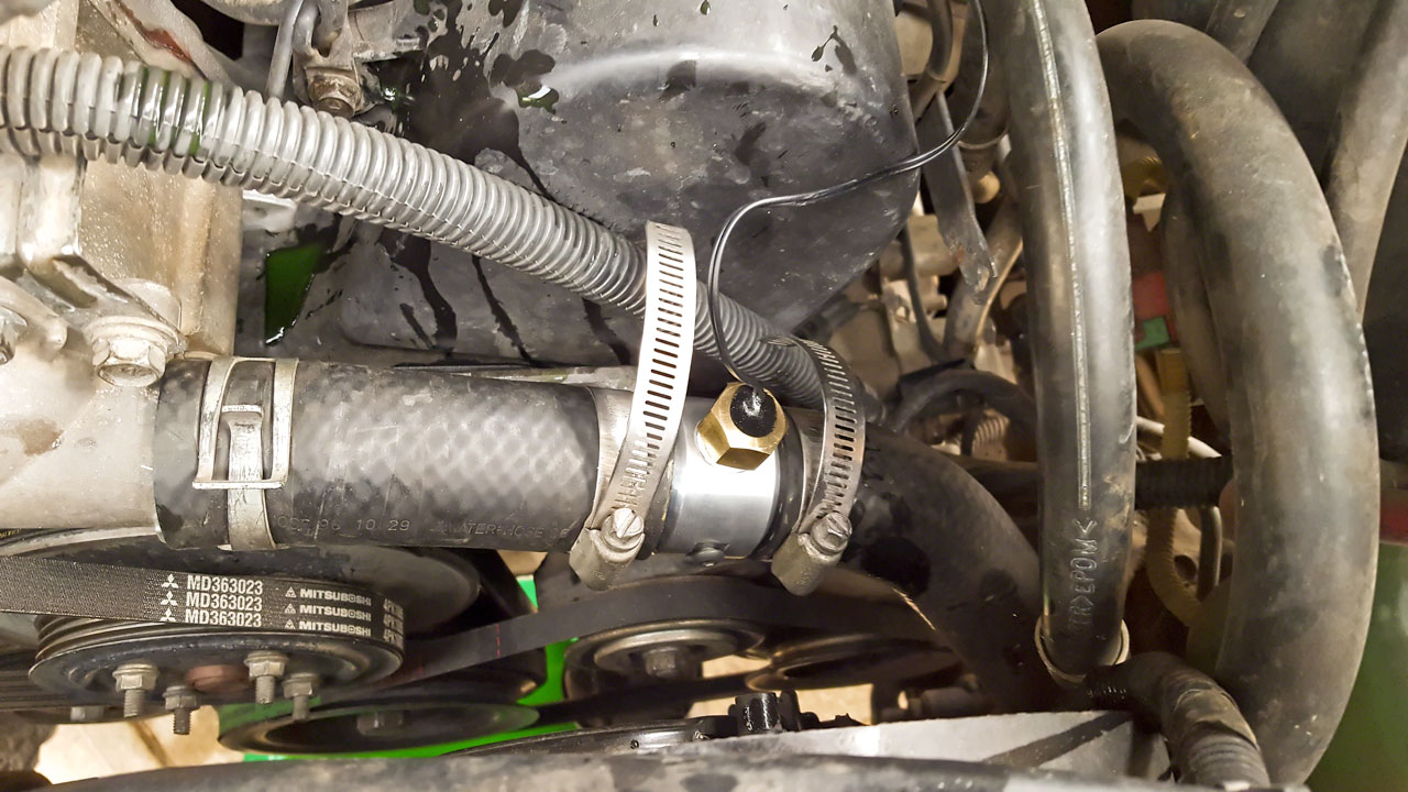
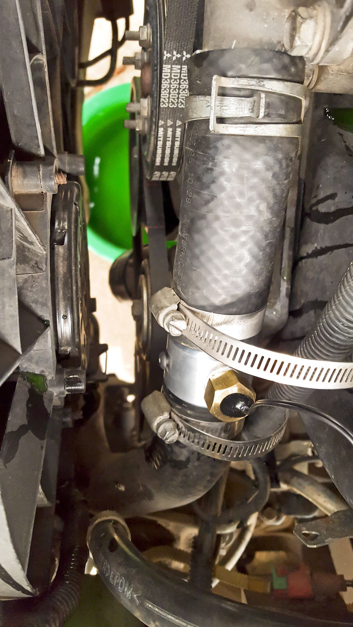
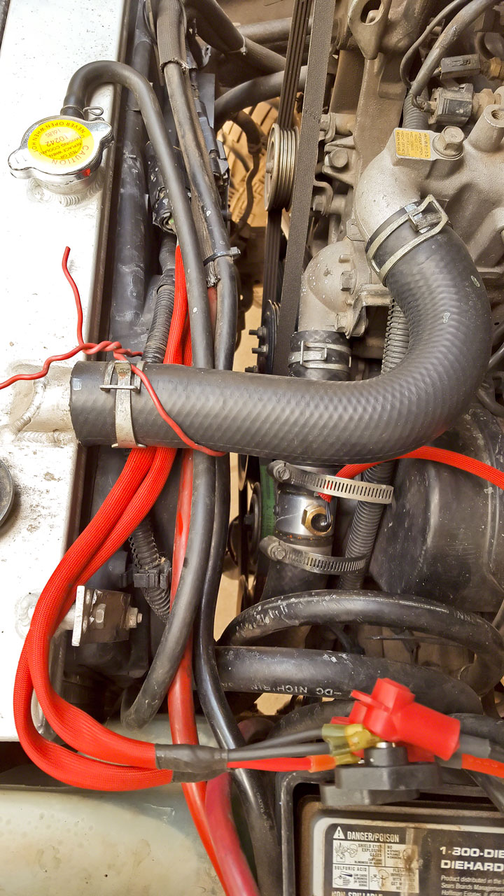
On to the sensor installation. I like the LCE Performance coolant hose manifold - in fact I like it better than my original one so I'm going to get another one for the '99 build. The 1 3/8" manifold fit perfectly - better than my 34mm manifold, in fact. A little Teflon tape, a big flare wrench and a little elbow grease and the sensor was installed in the manifold. This would have been a real bear to do after the manifold was installed in the hose.  While I was doing this, I had the radiator draining so I was ready to attack the lower hose by the time this was done. The bottom hose was new so I took a paint pen, marked the location of the manifold and how big a segment would need to be taken out of the hose, and used a razor knife to carefully cut out the 1.5' or so piece of hose. The first cut was easier with the hose installed. I took the top segment out for the second cut and replaced it when I was finished. Slid on a couple hose clamps, installed the manifold and tightened the clamps and that was it. The sensor comes with a plug that will not be used so I cut that off and then dangled the wire back over the engine where it wouldn't be in the way.
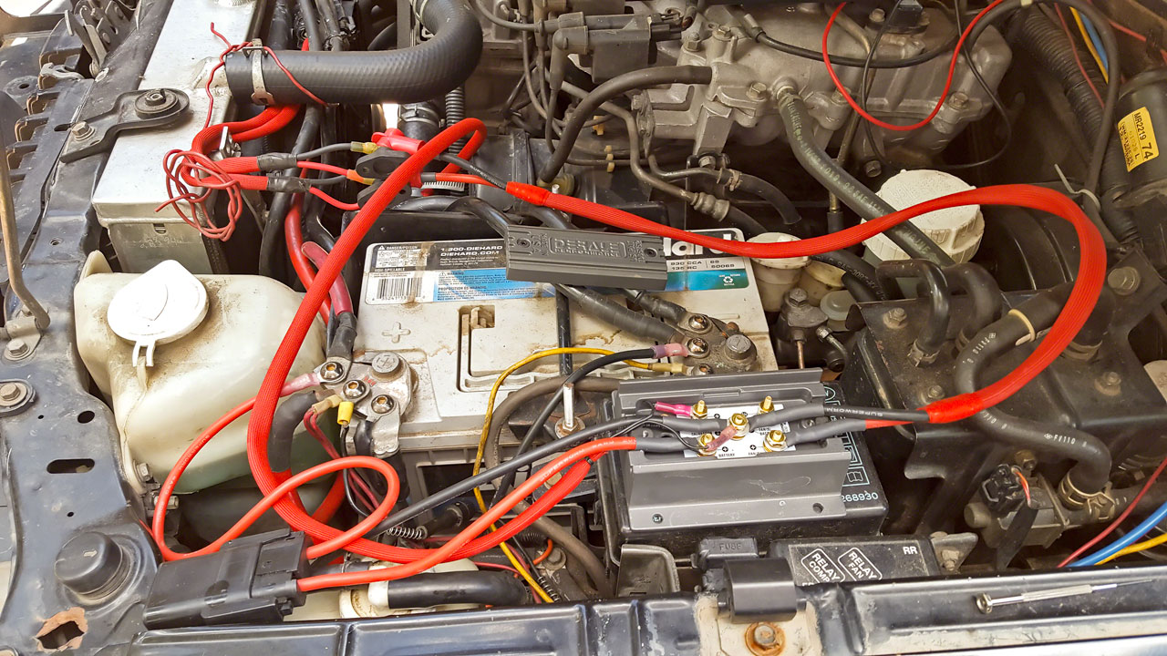
My plan is to attach the junction posts to the side of the plastic battery 'box' facing the engine, closest to the windshield washer bottle, then run the 8 AWG wire pair from the posts around the battery to the space between the windshield bottle and radiator over flow tank, behind the head light. That WAS the plan. The post location is good, but there is nowhere to mount the box anywhere in that location while hoping at any level to have access for adjustment. Gen 2 guys be thankful Mitsu relocated your windshield bottle. As of now, its wedged between the battery and the radiator over flow bottle. The Gen 1 is extremely limited in space in that area and I use a group 65 battery which makes the problem even worse. And there's nowhere flat. 'In The Future' I will probably have to fab some kind of sheet metal platform behind the headlight. We'll see.
At this point I have the fans wired to the controller and the general location where its going to live, so it was off to wire the controller to the battery. Positive side first, just 'cause I felt like it. A short run of 8 AWG from the battery to the fuse, and another short run from the fuse to the controller. My battery terminals use 3/8" ring terminals which again were from Ancor. I replaced the supplied circuit breaker with a 60 AMP, 8 AWG water tight fuse holder. (MAXX-DUTY Sealed Fuse Holder KIT) This is an off road vehicle which can be submerged up to the windows, so obviously Derale's circuit breaker, yet again, was not a good idea. The fuse holder is a kit and doesn't come with pre-installed leads. I also don't have the correct crimper for the terminal ends so I 'crimped' the wires to the terminals with a small pair of pliers making as tight a connection as I could get and then soldered the connection, finishing with the crimp on the insulation. There's no need to heat shrink these as the housing comes with seals. Once done, I added the #10 ring terminals to connect the whole thing to the controller. At the same time I tossed a spare 60 AMP fuse in the glove box. The negative wire was pretty anticlimactic. Two more ring terminals, one 3/8" and one #10 and the negative wire was finished. Again, I had to strip the heat shrink off both #10 ring terminals and replace it with thin wall heat shrink tubing.
Before I continued on, I test fit everything assembled up to this point in the controller and installed the lid. So far, all was well. I was still very glad I'd decided to consolidate the two fans into single 8 AWG runs.
The last piece was the sensor wiring. The last two connectors are simple 22-18 AWG #6 and #10 ring terminals. There is no positive or negative so no need to figure out what wire is which. The wire isn't very long. I ended up snipping off about 5" + whatever was attached to the plug when I cut that off. I intentionally left it a little long because I don't know exactly where the controller is going to go and a little length makes it easy to pull the controller and harness out and drape it back on the engine out of the way when work is being done. Unfortunately, unlike the SPAL, there is no way to unplug the sensor from the controller. One has to actually take the controller apart and remove the wires from the posts - nothing I want a tech to have to do. I also covered this wire with protective sheath. This is a very fine wire, very close to the hot engine. And, YET AGAIN, I had to cut the heat shrink tubing off the ring terminals and replace it with thin wall heat shrink tubing.
Ok. Now its time to tear it all back apart and run the wires, hook it all back up and test. Even with just the 'normal' number of terminals things are snug. I reinstalled the cover, moved everything around a little, repeated the process a couple times just to be sure and then tightened down the post nuts with the supplied lock washers. The only issues I had with this process was making sure that none of the ring terminals touched and making sure that the cover screws weren't rubbing on the wires exiting the controller. It wasn't difficult, but it did required some attention to detail. Back through once more to make sure everything was tight and then hook up the positive and negative wires to the battery.
Time to refill the radiator, warm up the engine and see if any of this actually works. Start to this point took about 12-13 hours. A far cry from the reviews claiming, 'I did the whole thing in an hour and a half!' I did a lot more than just 'slap it in', of course. Removal of the old SPAL setup, replacing the upper radiator hose, some unrelated wiring relocation, trying to figure out where the controller would go, fiddling with the fuse mounting, two rain showers and some other miscellaneous stuff. YMMV.
Anyway, I started the vehicle and let it sit warming up while I fired up the OBD scanner software to monitor the engine coolant temperature. Cigar and coffee time. I think the amount of time it takes for an engine to warm up is directly related to how late it is, how tired your are and how cold it is out. Three quarters of a cigar later the fans kick on at 199 degrees. Hmmmmm. The documentation says the fans are programmed for a thermostat that opens at 180. At this point its 2:00 in the morning. Do I mess with this or just leave it alone? Compromise. Take it for a short drive around the house and then its bed time. Worry about the details in the daylight.
At this point it'd warmed up and was holding stable at 194/196-ish it idle. A couple miles of driving around the development, a good mile up a steep road in 2WD-Lo-Lo managed to push it up into the low 200s @ 60 degrees ambient. Back down the hill and it immediately cooled down into the low 190s. Back up hill to the house drove it up into the low 200s and then back into the drive way. Ok, so far so good. About the same as the SPAL controller with one fan. Bed time.
The first step Sunday - tie back all the wires and check the controller adjustment. Don't trust Derale. Whatever it came set at wasn't anything in their documentation and sure wasn't '180'. :rolleyes: Somehow I just wasn't surprised. Out with the multi-meter. Derale is correct. It is super easy to adjust the controller - IF YOU HAVE THREE HANDS! Holding a probe on the test point, a probe on the negative post and trying to turn a potentiometer screw the size of a pin is a PITA. The LEAST they could have done was drill a small divot in the test point so the probe wouldn't keep sliding off.  Adjustment requires a micro screwdriver with like a 1mm blade. Thankfully I have a small collection of micro tools for fine electronics work. Derale doesn't supply a screwdriver - which they should - so this is a required tool most people probably don't' have. Thankfully, once this is set correctly, that's the last time it has to be fiddled with. Hopefully it doesn't take too many attempts to get it set correctly.
My controller came set somewhere between 180 and 190. A couple turns or so brought it up to 190. I had originally planned on starting at 193, but I forgot that part until I was backing out of the driveway. Rather than start over I figured I'd try it that way and if it seemed to drastically need changing I'd fiddle with it at the gas station. My first test was straight up the canyon into the Rockies. Unfortunately the weather wasn't cooperating. Temps were in the 60s and very low 70s. I was hoping for high 80s/low 90s but it was not to be. This is low speed 35-45 MPH up a reasonable grade for 7-8 miles. Usually enough to immediately bring to light any glaring issues. All seemed to be working. The temps seemed to be pretty steady between 199-203. From there is was up to the highway and over to 4th of July trail for a short 2 mile jaunt in 4WD-Lo-Lo. Nothing on the road and no issues on the trail. High temp seemed to be 203.
I figured if it was ok at this point, it was time for the long 250+ mile haul into northern CO and then back to the plains in a big 10 hour test loop of everything I can think of to make a vehicle overheat and everywhere it has had issues in the past. This included two passes - one paved and one trail, miles long uphill climbs at low/high speed, miles long down hill coast or near coast on and off pavement, and 2WD-Lo and 2WD-Lo-Lo on miles long 5-10 MPH climbs. And LOTs of long 55-75 MPH highway stretches. Ambient temps ranged between the high 50s and low 80s.
At no time did the ECT go above 208 degrees, no matter what I tried and believe me, I tried. That is something I can usually force at any time unless its below freezing. I really wish it had been much warmer - how this behaves when its 90+ is still a question. Also, CO isn't UT. There's a lot in UT that I can't replicate here. Still, this isn't any worse than my SPAL setup with one dead fan.
The fans turn off. Or get to the point that they're SO low they might as well be off. Having the temperature probe in the radiator outlet definitely has that advantage. The fans cycle on and off (or on and virtually off) a LOT more than the Spal setup. I can tell the fans are on, and on at a lower speed, a WHOLE LOT less than before. Which I think may be reflected in the mileage - but its too early to tell. It takes very little time on a down hill stretch before the fans cycle down to almost nothing or off. Very nice in the canyons where you're effectively coasting for 20-30+ miles.
For those reading, please KIM, that I have a radiator that has at least 3x the cooling capacity (and probably 3x the volume) of the OEM radiator and that will make a difference in how a controller with the probe in the radiator outlet cycles. YMMV with the OEM radiator.
I am not happy with the fact that the fans do not immediately shut off when the engine is turned off. Funny they don't seem to publicize that little detail. In all fairness, this is GREAT on a carbureted vehicle in a hot climate. My 'Bird is wired this way specifically to minimize fuel boiling out of a hot carburetor into the intake manifold, heads and cylinders. On a FI engine, this is largely useless. Yes, it helps cool down the engine and bay and that would be useful if it were 100+ degrees all the time. Maybe. But there is no timer on the controller. It relies strictly on the temperature probe to judge whether to shut off the fans. And that brings up another issue. With the probe in the hose rather than the radiator, that will take a while. In my experience, a lot longer than it takes with the probe in the radiator, if my 'Bird is any example. For obvious reasons, having fans draining the battery is probably not such a good idea. Another point, this means the controller is ALWAYS ACTIVE. That means the FANS are always hot, whether the ignition is on or off. If something goes haywire in the controller, it is entirely possible that the fans can turn on with the vehicle unattended and run the battery dead.
This is a great, half way, implemented 'feature'. EITHER put a ignition shut off circuit in place OR put the shut off on a timer. Honestly, I could live with either one but nothing is just stupid. As previously noted, I run a group 65 AGM battery with a huge alternator. This is a PWM controller so the fans will not continue on 100% indefinitely with the engine off. Risk for me is probably low. I think. We'll see. This is just not a very good feature for a vehicle that gets used like mine does.
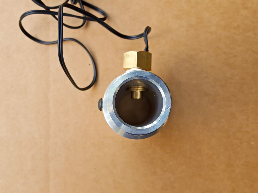
Derale also sells a probe 'adapter'. This is the adapter that is supposed to be used with the screw-in body thermistor that comes with the controller. Its basically a 3/8" bung with a screw hole in the top for the thermistor body. The height of Derale technology. Oh, boy. :rolleyes: AFAIKT, the sensor I purchased from Derale - which is not the same - works fine. It is certainly designed better. There are two major drawbacks to using their 'official' adapter. #1 - The thermistor is in the body, not the bung. Anything that heats up the body, like having mounted in the hose 1" from the engine block, is going to seriously skew the temperature readings. Or in reverse - having cold air blowing on the body will skew it the other directions. #2 - the 'adapter' or bung isn't even a probe. Its a BUNG. Nothing actually extends into the coolant flow. This design will be skewed by the temperature of the coolant hose manifold. See #1. :rolleyes: #3 - at whatever poor level this works at, the readings are going to be DIRT SLOW. That is a lot of metal for heat to transfer through before reaching the body and then the thermistor encased within.
The unofficial probe, however, seems to be working fine. Fans ramp up, fans ramp down, temperature seems to behave as one would expect - well, as I would expect in this vehicle, anyway. Unless there's something I'm missing here - which I don't think I am since everything seems to be working - I'm sticking with the probe I'm using.
Oh, and again, since there's no way to shut off the fans, this is probably a bad setup for a vehicle that does deep water crossings.
At this point I'm not unhappy with the product. I'm ambivalent. It works. More or Less. I'm not surprised with things like the supplied probe, adapter or install kit. This has been my experience with Derale for going on 20 years. They ALMOST make a good product...but then they don't. For a US company, this is distinctly Chinese-like. The only redeeming feature of this controller, given that, is the price. I would have been really upset if I had to add $100 in parts to a $300 controller to make it work correctly and be able to install it. As it stands, I've spent about $250 in total.
What this controller does have to recommend it, is its simplicity. It is DIRT simple to install and use. There are no extra switches, no convoluted wiring, nothing. If the controller fails for any reason, I can disconnect the positive fan lead from the controller fan post and reattach it at the positive battery post and I have fans. So, bypassing the controller in an emergency is a couple minute job. I can't say that for any other PWM controller besides DC Control. And since the only setting happens to be roughly the thermostat opening temperature, there's almost no way to screw up setting the controller correctly.
I have a call planed to Derale tech support tomorrow to ask some follow-up questions:
1) How to turn off the fans when the engine shuts off
2) Their official position on the 16750 temp probe
3) In what state do the fans fail if the probe isn't working
And, I'll get pictures posted up here ASAP.
Additional information -
Need feedback on electric radiator fan controlers
Edward
On with it then ...

Listed below are all the parts and tools I used in the installation. Having previously done installations like this before, and having previously dealt with Derale's 'install kits', and after doing a lot of research on this particular kit, I had a fairly good idea what wouldn't work, what was garbage and what needed to be changed for my application.
Parts -
Derale 16750 3/8" Replacement NPT Thread-In Probe
Derale 16795 PWM Fan Controller
Taylor Cable 2582 Red Thermal Protector Sleeving
Superworm 8 Gauge Silicone Wire Super Flexible by ACER Racing 5' Red/5' Black
Blue Sea Systems Mini PowerPost with 10-32-Inch Stud
Ancor Marine Grade Electrical Nylon Insulated Adhesive Lined Heat Shrink Ring Terminals (12 to 10-Gauge, Size 10 Screw)
Ancor Marine Grade Electrical Nylon Insulated Adhesive Lined Heat Shrink Ring Terminals (22 to 18-Gauge, Size 8 Screw)
Ancor Marine Grade Products 8 AWG #10 Heat Shrink Ring Terminals
Ancor Marine Grade Products 8 AWG Heat Shrink Ring Terminals 3/8"
109154 MAXX-DUTY 60 AMP Sealed Fuse Holder KIT (DIY)
BLUE SEA 5141 FUSE MAXI 60 AMP
Pico 2210PT 22-16 AWG Electrical Wiring Heat Shrink #6 Ring / Eye Terminals
Teflon tape
Thin/medium wall heat shrink tubing
1 3/8" coolant hose manifold w/ 3/8" NPT sensor port
2 hose clamps
Tools -
BIG electric soldering iron or Butane soldering torch
Electrical solder
Wire stripper/crimper
Hydraulic Cable Lug Crimper
Small SAE hex wrench
Small 1/4" drive SAE socket set
A REALLY small screwdriver
I should point out now why the parts list is so large. While the controller itself appears to be good quality, the installation kit is IMHO, cheap garbage. The 10 AWG wire doesn't appear to actually be 10 AWG. Its appears smaller (like 11 AWG if there were such a thing) and its very few, very thick strands - a hallmark of cheap electrical wiring. It was sufficient for a 10-12" run, but there is NO WAY I'd do an entire installation with that wire.
 The terminals are just cheap auto parts store grade crimp connectors and IMHO not up to carrying upwards of 30 AMPS - especially with eyelets that small. The resetting circuit breaker has NO protection. NO cover, NO terminal covers, nothing. SERIOUSLY?!
 The Installation -
The Derale wiring directions are reasonably straight forward. It is clear, though, that while this controller will drive two Contour fans, the controller itself wasn't designed with dual fans in mind. The terminals are very close together - trying to run four 10 AWG wires to the controller isn't a good idea if its even possible, and four 8 AWG wires wouldn't be possible at all.
So, the first thing I did was patch some of the 10 AWG wire into the OEM plug harness with four ring terminals so that I could attach those wires to junction posts. (Blue Sea Systems Mini PowerPost) The 10 AWG was soldered to the OEM pig tails, sealed with shrink tubing and then the whole thing covered in a protective sheath. (Taylor Cable Red Thermal Protector Sleeving) The ring terminals came with heat shrink tubing with the glue inside to completely seal the connection.
The controller has two positive (+) terminals and ONE negative (-) terminal, in a very small space. With a dual fan setup using 10 AWG from the fans, this would require 2 positive and 2 negative wires coming in one side of the controller. The two negative wires from the fans would go to the same post in the controller, which has a third running to the negative battery terminal AND another ring terminal for the sensor. This is FOUR terminals connecting to the same TINY post. Trying to get all those connectors in that small a space without ending up with an electrical short is problematic.
Running the 10 AWG fans wires to two junction posts and then running two 8 AWG wires to the controller was very clean and minimized the number of ring terminals in the controller.The next step was running the 8 AWG from the junction posts to the controller. Easy-peasy. Uh, no. Big mistake #1.
All the ring terminals wouldn't fit in the controller. Or on the junction posts. I really like Ancor's marine grade terminals. Their tinned and use heavy duty heat shrink with the glue inside. Which, unfortunately, makes them bulky. Step #1 - heat up the heat shrink after making the crimp and cut the heat shrink off with a razor knife. Step #2 - dig through my box of thin wall heat shrink tubing and heat shrink the four ring terminals. Problem solved. The thin walled heat shrink was perfect - it insulated the terminals from each other in the controller and added minimal bulk so that the boots on the junction posts fit correctly and the cover on the Derale controller closed and sealed. Stupid mistake #2. I ordered #10 ring terminals instead of #8 ring terminals for the controller end of the 8 AWG wires. Thankfully there's a VERY small difference between #8 and #10 so I could use the 8 AWG #10 terminals. Really stupid mistake #3. I forgot to put the wire sheath on BEFORE putting on all the ring terminals. It took 30 minutes but I finally, BARELY, managed to get both wires into the sheath. It sucked. A lot. On to the sensor installation. I like the LCE Performance coolant hose manifold - in fact I like it better than my original one so I'm going to get another one for the '99 build.
The 1 3/8" manifold fit perfectly - better than my 34mm manifold, in fact. A little Teflon tape, a big flare wrench and a little elbow grease and the sensor was installed in the manifold. This would have been a real bear to do after the manifold was installed in the hose.  While I was doing this, I had the radiator draining so I was ready to attack the lower hose by the time this was done. The bottom hose was new so I took a paint pen, marked the location of the manifold and how big a segment would need to be taken out of the hose, and used a razor knife to carefully cut out the 1.5' or so piece of hose. The first cut was easier with the hose installed. I took the top segment out for the second cut and replaced it when I was finished. Slid on a couple hose clamps, installed the manifold and tightened the clamps and that was it. The sensor comes with a plug that will not be used so I cut that off and then dangled the wire back over the engine where it wouldn't be in the way.
My plan is to attach the junction posts to the side of the plastic battery 'box' facing the engine, closest to the windshield washer bottle, then run the 8 AWG wire pair from the posts around the battery to the space between the windshield bottle and radiator over flow tank, behind the head light. That WAS the plan. The post location is good, but there is nowhere to mount the box anywhere in that location while hoping at any level to have access for adjustment. Gen 2 guys be thankful Mitsu relocated your windshield bottle.
As of now, its wedged between the battery and the radiator over flow bottle. The Gen 1 is extremely limited in space in that area and I use a group 65 battery which makes the problem even worse. And there's nowhere flat. 'In The Future' I will probably have to fab some kind of sheet metal platform behind the headlight. We'll see.At this point I have the fans wired to the controller and the general location where its going to live, so it was off to wire the controller to the battery. Positive side first, just 'cause I felt like it.
A short run of 8 AWG from the battery to the fuse, and another short run from the fuse to the controller. My battery terminals use 3/8" ring terminals which again were from Ancor. I replaced the supplied circuit breaker with a 60 AMP, 8 AWG water tight fuse holder. (MAXX-DUTY Sealed Fuse Holder KIT) This is an off road vehicle which can be submerged up to the windows, so obviously Derale's circuit breaker, yet again, was not a good idea. The fuse holder is a kit and doesn't come with pre-installed leads. I also don't have the correct crimper for the terminal ends so I 'crimped' the wires to the terminals with a small pair of pliers making as tight a connection as I could get and then soldered the connection, finishing with the crimp on the insulation. There's no need to heat shrink these as the housing comes with seals. Once done, I added the #10 ring terminals to connect the whole thing to the controller. At the same time I tossed a spare 60 AMP fuse in the glove box. The negative wire was pretty anticlimactic. Two more ring terminals, one 3/8" and one #10 and the negative wire was finished. Again, I had to strip the heat shrink off both #10 ring terminals and replace it with thin wall heat shrink tubing.Before I continued on, I test fit everything assembled up to this point in the controller and installed the lid. So far, all was well. I was still very glad I'd decided to consolidate the two fans into single 8 AWG runs.
The last piece was the sensor wiring. The last two connectors are simple 22-18 AWG #6 and #10 ring terminals. There is no positive or negative so no need to figure out what wire is which. The wire isn't very long. I ended up snipping off about 5" + whatever was attached to the plug when I cut that off. I intentionally left it a little long because I don't know exactly where the controller is going to go and a little length makes it easy to pull the controller and harness out and drape it back on the engine out of the way when work is being done. Unfortunately, unlike the SPAL, there is no way to unplug the sensor from the controller. One has to actually take the controller apart and remove the wires from the posts - nothing I want a tech to have to do. I also covered this wire with protective sheath. This is a very fine wire, very close to the hot engine. And, YET AGAIN, I had to cut the heat shrink tubing off the ring terminals and replace it with thin wall heat shrink tubing.
Ok. Now its time to tear it all back apart and run the wires, hook it all back up and test. Even with just the 'normal' number of terminals things are snug. I reinstalled the cover, moved everything around a little, repeated the process a couple times just to be sure and then tightened down the post nuts with the supplied lock washers. The only issues I had with this process was making sure that none of the ring terminals touched and making sure that the cover screws weren't rubbing on the wires exiting the controller. It wasn't difficult, but it did required some attention to detail. Back through once more to make sure everything was tight and then hook up the positive and negative wires to the battery.
Time to refill the radiator, warm up the engine and see if any of this actually works. Start to this point took about 12-13 hours. A far cry from the reviews claiming, 'I did the whole thing in an hour and a half!'
I did a lot more than just 'slap it in', of course. Removal of the old SPAL setup, replacing the upper radiator hose, some unrelated wiring relocation, trying to figure out where the controller would go, fiddling with the fuse mounting, two rain showers and some other miscellaneous stuff. YMMV. Anyway, I started the vehicle and let it sit warming up while I fired up the OBD scanner software to monitor the engine coolant temperature. Cigar and coffee time. I think the amount of time it takes for an engine to warm up is directly related to how late it is, how tired your are and how cold it is out.
Three quarters of a cigar later the fans kick on at 199 degrees. Hmmmmm. The documentation says the fans are programmed for a thermostat that opens at 180. At this point its 2:00 in the morning. Do I mess with this or just leave it alone? Compromise. Take it for a short drive around the house and then its bed time. Worry about the details in the daylight. At this point it'd warmed up and was holding stable at 194/196-ish it idle. A couple miles of driving around the development, a good mile up a steep road in 2WD-Lo-Lo managed to push it up into the low 200s @ 60 degrees ambient. Back down the hill and it immediately cooled down into the low 190s. Back up hill to the house drove it up into the low 200s and then back into the drive way. Ok, so far so good. About the same as the SPAL controller with one fan. Bed time.
The first step Sunday - tie back all the wires and check the controller adjustment. Don't trust Derale.
Whatever it came set at wasn't anything in their documentation and sure wasn't '180'. :rolleyes: Somehow I just wasn't surprised. Out with the multi-meter. Derale is correct. It is super easy to adjust the controller - IF YOU HAVE THREE HANDS! Holding a probe on the test point, a probe on the negative post and trying to turn a potentiometer screw the size of a pin is a PITA. The LEAST they could have done was drill a small divot in the test point so the probe wouldn't keep sliding off.  Adjustment requires a micro screwdriver with like a 1mm blade. Thankfully I have a small collection of micro tools for fine electronics work. Derale doesn't supply a screwdriver - which they should - so this is a required tool most people probably don't' have. Thankfully, once this is set correctly, that's the last time it has to be fiddled with. Hopefully it doesn't take too many attempts to get it set correctly.
My controller came set somewhere between 180 and 190. A couple turns or so brought it up to 190. I had originally planned on starting at 193, but I forgot that part until I was backing out of the driveway.
Rather than start over I figured I'd try it that way and if it seemed to drastically need changing I'd fiddle with it at the gas station. My first test was straight up the canyon into the Rockies. Unfortunately the weather wasn't cooperating. Temps were in the 60s and very low 70s. I was hoping for high 80s/low 90s but it was not to be. This is low speed 35-45 MPH up a reasonable grade for 7-8 miles. Usually enough to immediately bring to light any glaring issues. All seemed to be working. The temps seemed to be pretty steady between 199-203. From there is was up to the highway and over to 4th of July trail for a short 2 mile jaunt in 4WD-Lo-Lo. Nothing on the road and no issues on the trail. High temp seemed to be 203.I figured if it was ok at this point, it was time for the long 250+ mile haul into northern CO and then back to the plains in a big 10 hour test loop of everything I can think of to make a vehicle overheat and everywhere it has had issues in the past. This included two passes - one paved and one trail, miles long uphill climbs at low/high speed, miles long down hill coast or near coast on and off pavement, and 2WD-Lo and 2WD-Lo-Lo on miles long 5-10 MPH climbs. And LOTs of long 55-75 MPH highway stretches. Ambient temps ranged between the high 50s and low 80s.
At no time did the ECT go above 208 degrees, no matter what I tried and believe me, I tried.
That is something I can usually force at any time unless its below freezing. I really wish it had been much warmer - how this behaves when its 90+ is still a question. Also, CO isn't UT. There's a lot in UT that I can't replicate here. Still, this isn't any worse than my SPAL setup with one dead fan. The fans turn off. Or get to the point that they're SO low they might as well be off. Having the temperature probe in the radiator outlet definitely has that advantage. The fans cycle on and off (or on and virtually off) a LOT more than the Spal setup. I can tell the fans are on, and on at a lower speed, a WHOLE LOT less than before. Which I think may be reflected in the mileage - but its too early to tell. It takes very little time on a down hill stretch before the fans cycle down to almost nothing or off. Very nice in the canyons where you're effectively coasting for 20-30+ miles.
For those reading, please KIM, that I have a radiator that has at least 3x the cooling capacity (and probably 3x the volume) of the OEM radiator and that will make a difference in how a controller with the probe in the radiator outlet cycles. YMMV with the OEM radiator.
I am not happy with the fact that the fans do not immediately shut off when the engine is turned off.
Funny they don't seem to publicize that little detail. In all fairness, this is GREAT on a carbureted vehicle in a hot climate. My 'Bird is wired this way specifically to minimize fuel boiling out of a hot carburetor into the intake manifold, heads and cylinders. On a FI engine, this is largely useless. Yes, it helps cool down the engine and bay and that would be useful if it were 100+ degrees all the time. Maybe. But there is no timer on the controller. It relies strictly on the temperature probe to judge whether to shut off the fans. And that brings up another issue. With the probe in the hose rather than the radiator, that will take a while. In my experience, a lot longer than it takes with the probe in the radiator, if my 'Bird is any example. For obvious reasons, having fans draining the battery is probably not such a good idea. Another point, this means the controller is ALWAYS ACTIVE. That means the FANS are always hot, whether the ignition is on or off. If something goes haywire in the controller, it is entirely possible that the fans can turn on with the vehicle unattended and run the battery dead.This is a great, half way, implemented 'feature'. EITHER put a ignition shut off circuit in place OR put the shut off on a timer. Honestly, I could live with either one but nothing is just stupid. As previously noted, I run a group 65 AGM battery with a huge alternator. This is a PWM controller so the fans will not continue on 100% indefinitely with the engine off. Risk for me is probably low. I think. We'll see. This is just not a very good feature for a vehicle that gets used like mine does.
Derale also sells a probe 'adapter'. This is the adapter that is supposed to be used with the screw-in body thermistor that comes with the controller. Its basically a 3/8" bung with a screw hole in the top for the thermistor body. The height of Derale technology. Oh, boy. :rolleyes:
AFAIKT, the sensor I purchased from Derale - which is not the same - works fine. It is certainly designed better. There are two major drawbacks to using their 'official' adapter. #1 - The thermistor is in the body, not the bung. Anything that heats up the body, like having mounted in the hose 1" from the engine block, is going to seriously skew the temperature readings. Or in reverse - having cold air blowing on the body will skew it the other directions. #2 - the 'adapter' or bung isn't even a probe. Its a BUNG. Nothing actually extends into the coolant flow. This design will be skewed by the temperature of the coolant hose manifold. See #1. :rolleyes: #3 - at whatever poor level this works at, the readings are going to be DIRT SLOW. That is a lot of metal for heat to transfer through before reaching the body and then the thermistor encased within.The unofficial probe, however, seems to be working fine. Fans ramp up, fans ramp down, temperature seems to behave as one would expect - well, as I would expect in this vehicle, anyway.
Unless there's something I'm missing here - which I don't think I am since everything seems to be working - I'm sticking with the probe I'm using.Oh, and again, since there's no way to shut off the fans, this is probably a bad setup for a vehicle that does deep water crossings.
At this point I'm not unhappy with the product. I'm ambivalent. It works. More or Less. I'm not surprised with things like the supplied probe, adapter or install kit. This has been my experience with Derale for going on 20 years. They ALMOST make a good product...but then they don't. For a US company, this is distinctly Chinese-like. The only redeeming feature of this controller, given that, is the price. I would have been really upset if I had to add $100 in parts to a $300 controller to make it work correctly and be able to install it. As it stands, I've spent about $250 in total.
What this controller does have to recommend it, is its simplicity. It is DIRT simple to install and use. There are no extra switches, no convoluted wiring, nothing. If the controller fails for any reason, I can disconnect the positive fan lead from the controller fan post and reattach it at the positive battery post and I have fans. So, bypassing the controller in an emergency is a couple minute job. I can't say that for any other PWM controller besides DC Control. And since the only setting happens to be roughly the thermostat opening temperature, there's almost no way to screw up setting the controller correctly.
I have a call planed to Derale tech support tomorrow to ask some follow-up questions:
1) How to turn off the fans when the engine shuts off
2) Their official position on the 16750 temp probe
3) In what state do the fans fail if the probe isn't working
And, I'll get pictures posted up here ASAP.
Additional information -
Need feedback on electric radiator fan controlers
Edward