Post by ES_97Sport on Nov 7, 2016 22:05:45 GMT -5
I know there are a bunch of threads, so here's another one. 
Part 1 - Fans
Part 2 - Controller
Derale 16795 PWM Fan Controler Installation
Electric fan contour swap
Part 3 - Installation
I'm not gong to bother with 'part 2' as that's pretty well (recently) documented, but I figured I might as well update parts 1 and 3.
Anyway, part 1 ...
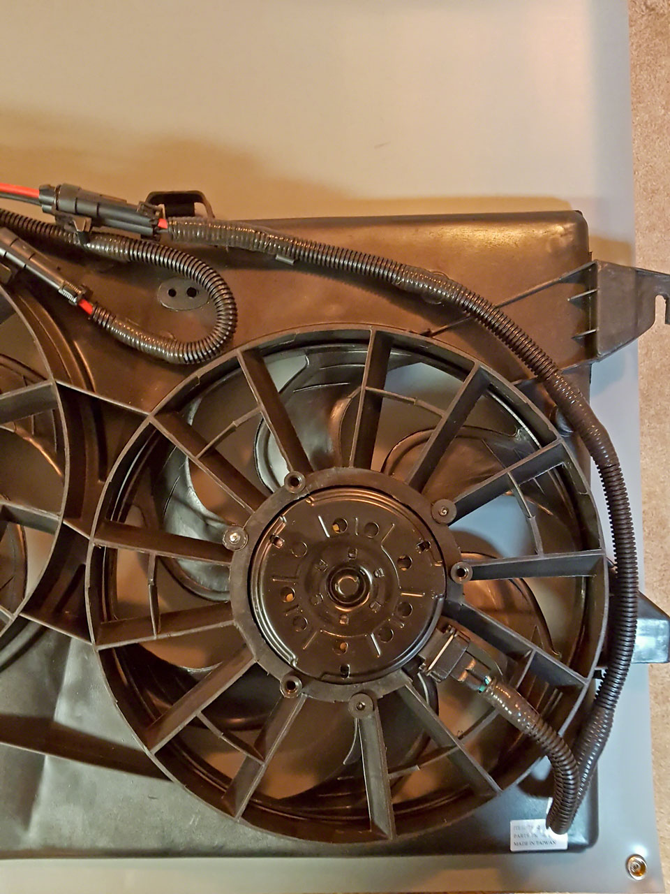
I gave up trying to find an intact Contour fan assembly from the salvage yards, ebay or CL. The vehicles are just too old and too thrashed. Instead I bought an entire replacement assembly. Hopefully this one will last for a while as its from Taiwan rather than China.
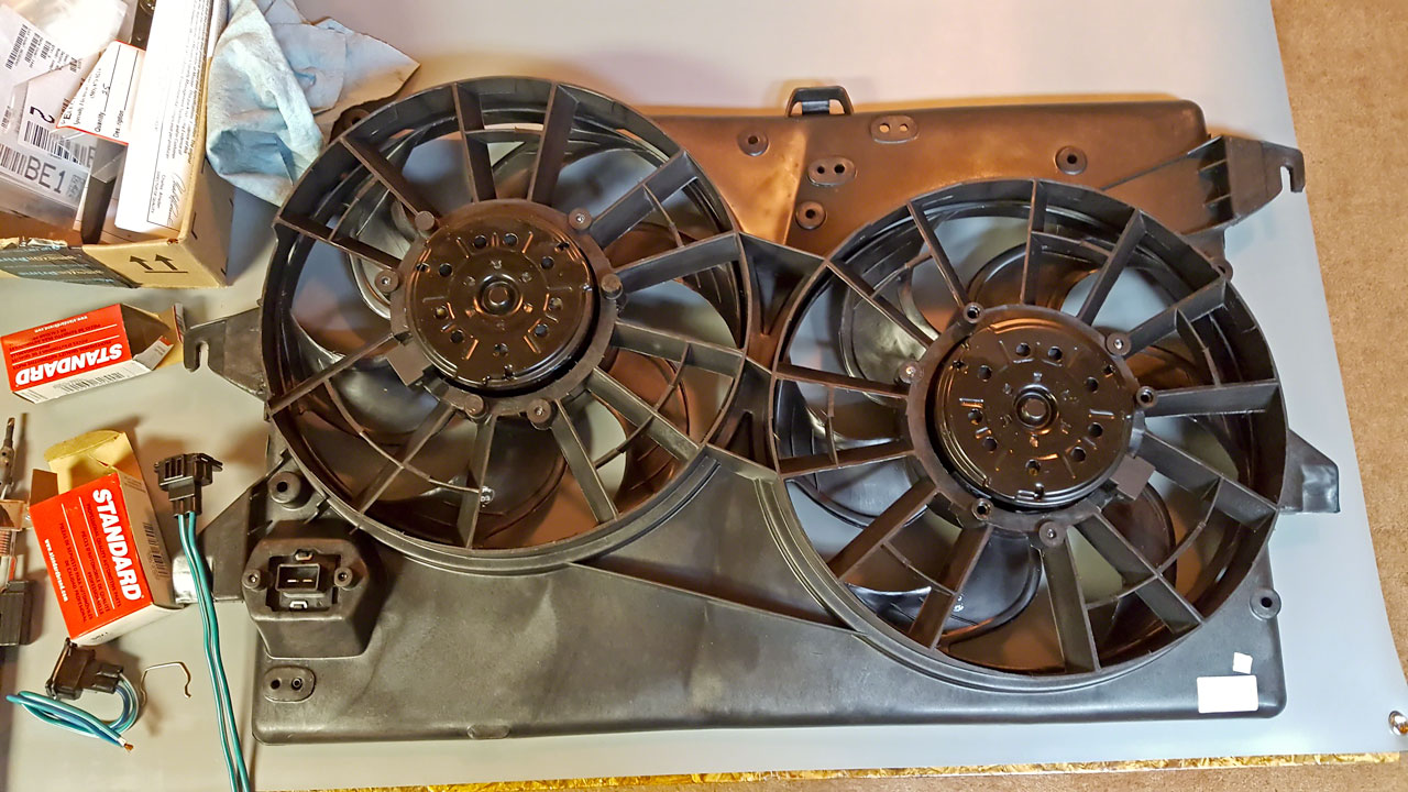
Similarly the harnesses are also thrashed. I had no interest in wasting an entire weekend - again - hunting for the fan motor and assembly connectors - which were really the only pieces I wanted anyway. The last time I did this, it took me longer to rebuild the Ford harness than it would have to build my own but the connectors were not commonly available 5-6 years ago. Now the motor connectors can be sourced from Amazon, eBay, Napa and pretty much every other auto parts supplier I looked at.
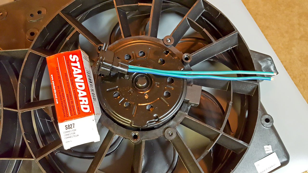
I settled on the General S827 connector off Amazon. They were cheap and I had 'points'. The connector looked to be decently made - time will tell. I wasn't happy, however, to find out that the pigtails were 12AWG. I was really hoping for 10AWG, but ....
The two OEM connectors at the top of the fan assembly that the main vehicle wiring harness plugs into are brutes. At the time of the building of my first Contour setup, connectors that would handle the amperage of the Contour fan motors were very difficult to source. This time a little searching led me to the Delphi Metri-Pack 480 rated at 42 amps. The terminals are 12-10AWG. The only downside is the requirement of a specific crimper for the larger terminals. My existing Delphi crimper only goes down to 14AWG. You can't 'fake' it - if you don't have the correct crimper you will have issues.
Female connector - 12052613
Female terminal - 12052139-L
Male connector - 12065863
Male terminal - 12052172-L
Secondary lock - 12059897
Weather seals (purple) - 12052453
Hand crimper - 12071687 (12-10 GA Metri-Pack 480 & 630 Series terminals)
(Source: Mouser.com, theElectricalDepot.com)
The last three pieces were heat shielding for the wires, attachment clips and wire.
I had plenty of high temp 10AWG stranded red/black wire so that was easy. I used thicker strand, stiffer wire for the fan shroud harness. The attachment points on the shroud are a ways apart and I didn't want stuff flopping around and didn't feel like drilling 1/4" holes every 6". The stiffer wire worked out well - but was kind of a PITA to work with.
I've run across this problem multiple times, even on OEM harnesses. I settled on using the corrugated plastic split loom wire covering. The stuff you see EVERYWHERE on wiring projects. The problem? The cheap nickle-a-foot multicolored stuff that every auto part and hardware store carries isn't made to go under the hood of a vehicle and it doesn't take long before it starts falling apart and/or melting. Wedging the cheep stuff between the radiator and engine block is not a good plan if you're looking for a long and trouble free installation.
I opted for the black corrugated cover with the grey stripe. There are a couple types of the black tubing and two have a stripe. The blue stripe indicates its flame retardant but the temperature rating is only 200F. The gray strip indicates its high temperature and is rated to 300F. As best as I can tell all black is 200F and some colored protector is also 200F - not high enough for exposure next to an engine.
The black with gray strip isn't hard to find but its hard to identify on the internet sites and most want to sell you 50' or 100' - WAY more than I needed. I love McMASTER-CARR - 5, 25, 50 and 100'. I used 3/8" ID which fit the 10AWG great - except I forgot to take into account the diameter of the splices from the 12AWG connector pig-tails to the 10AWG wire + the double-wall shrink wrap. Sigh. Well, actually I did, I just forgot to stagger my splices. Without the shrink wrap, everything fit fine - with the shrink wrap the splices barely fit. Mostly. Close enough that I wasn't willing to redo two splices.
High-Strength Slit Corrugated Sleeving 3/8"ID
(Source: McMaster-Carr.com)
The last thing was rosebuds to attach the corrugated loom to the fan shroud. Which turned out to be a flaming PITA. I used the standard snap-closed round clips on the last fan build and I didn't like them. The part that snapped into the shroud was too small for the 1/4" hole and no matter what I did - short of installing a bunch more clips - everything flops around. What I WANTED was the tape on rosebuds.
Eventually my search led me back to Mouser and after a little research on their site, I found what I was looking for. These are just like the OEM ones you see on harnesses. Position the rosebud, wrap a couple winds of tape around both ends and snap it in. These are not useful for quick removal of a harness but they're more compact and nicer (IMHO) for a semi-permanent installation. And they don't snag on stuff which was a big plus for me.
Delphi 08911496-B
(Source: Mouser.com)
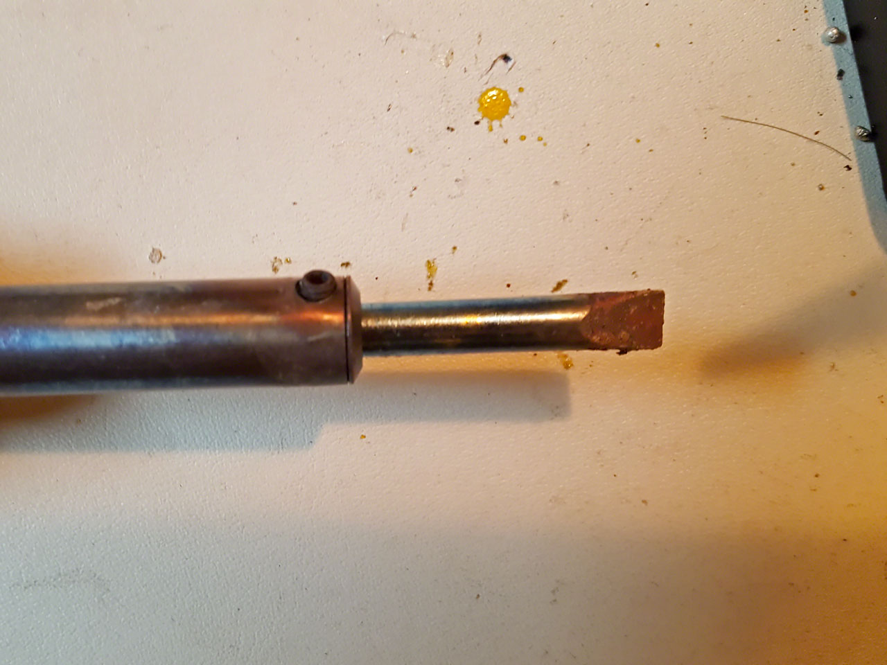
Misc stuff you need - A GOOD electric (or butane) soldering iron with the appropriate tip. A little 75W from Radio Shack isn't going to cut it when soldering 12AWG to 10AWG, nor is the little needle tip used for fine electronics work. I use a large 'chisel' tip and crank up the temperature.
Also, some good double-walled shrink tube with the adhesive inside. DO NOT just use electrical tape on these splices! These four splices (pos & neg for 2 motors) are going to see a LOT of heat, road crud, water, deicer, vibration and God knows what else over time. The splices need to be permanently sealed.
Rather than regular electrical tape to dress up the loom, I used the high temp self-fusing tape. No glue to break down or melt and become a gooey mess and it doesn't harden up and crack and break. I used the same on my first fan build and that's worked well for a number of years.
Self-Fusing Tape 1" 10yds - 7643A79
(Source: McMaster-Carr.com)
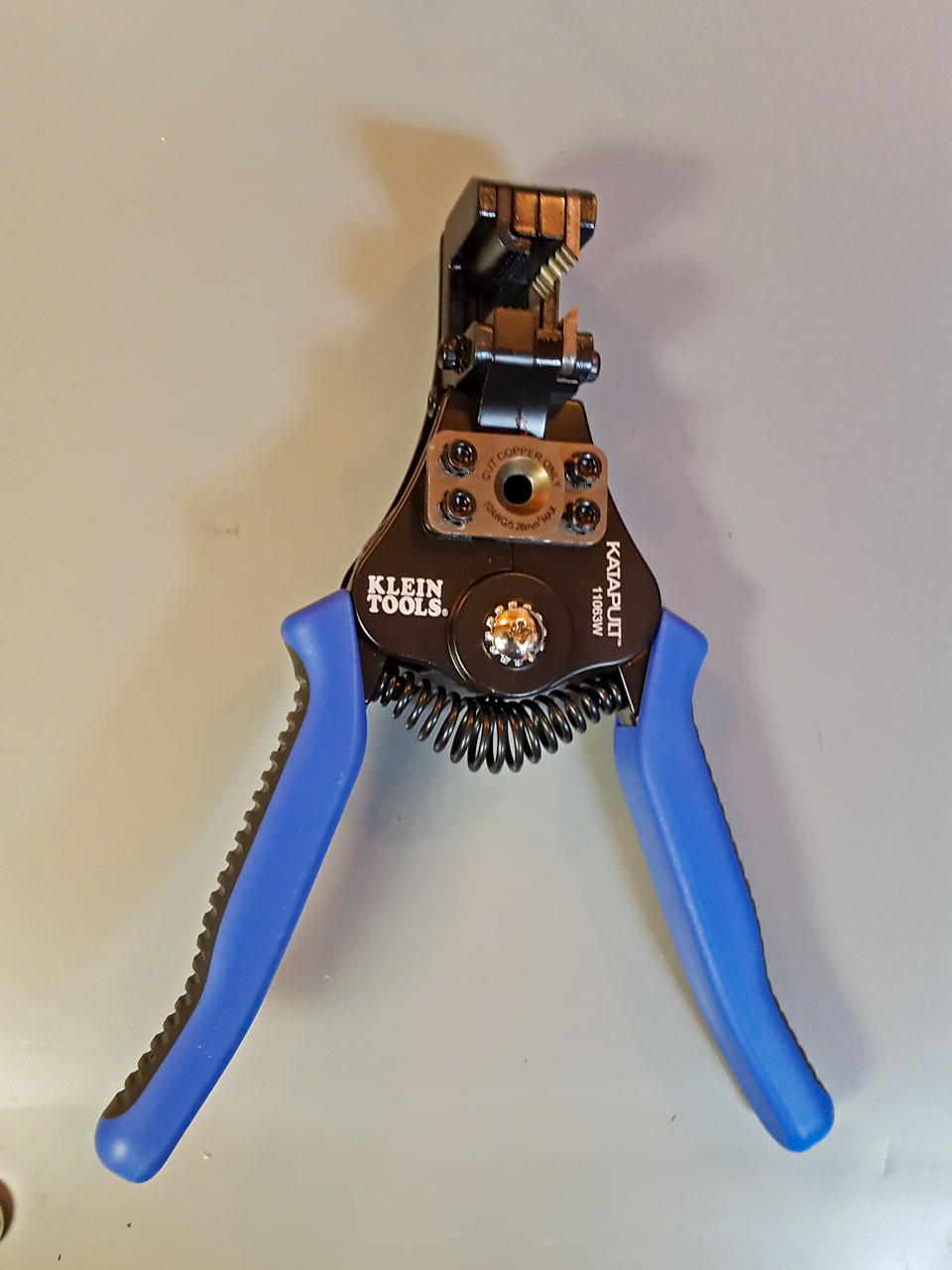
A good wire stripper that will do 8, 10 and 12AWG isn't a necessity but it sure makes the job easier. I have several wire strippers - all of which work good on one or two sizes but suck on the others. Since I have a LOT of wiring to do on this build, I decided to get a really good stripper that would work on everything. The Klein Katapult Wire Stripper costs about what two of my others cost and so far has worked flawlessly on 10, 12 and 22AWG (silicone and PVC insulation). It does not, however, work on the super fine strand 8AWG from CE.
Klein Tools 11063W 8-22 AWG Katapult Wire Stripper
(Source: Amazon.com)
Onwards ...
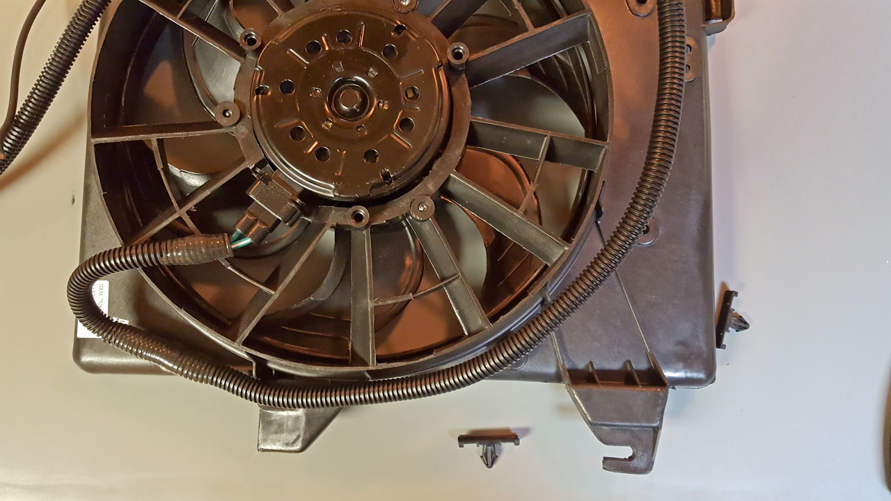
Because I've long since forgotten, I started by taking one of motor connectors and plugging it in to the fan motor and then connecting the leads to a battery so I could figure out which lead was positive and which was negative. When looking into the connector on the fan motor, with the shaft (fan blades) pointed down towards the floor, the blade on the right will be pos and the left neg. In the case of my connectors, the positive was the green w/ white stripe.
After figuring that out, it was time to splice the connector into the 10AWG wire. Again, unless you're planning on using larger than 3/8"ID wire protector, you will want to stagger the splices. Splicing together wire this large isn't rocket surgery, but it isn't as easy as two pieces of 18AWG, either. I strip 1" from both ends and do a slightly short Lineman splice. (see pg 71 PDF linked to below) If you want something to practice when you're bored that will come in handy latter, see page 69.
NASA TECHNICAL STANDARD - WORKMANSHIP STANDARD FOR CRIMPING, INTERCONNECTING CABLES, HARNESSES, AND WIRING
A tip for those who are new to soldering - DO NOT move the wires while or right after soldering. I do all my work on my workbench with a '3rd set of hands' - which is basically a stand with several flexible arms and alligator clips. Its almost impossible if you're inexperienced to solder a joint while holding the solder with one hand and the iron with the other if the wires are not held steady, and once you have the joint soldered and you've removed the iron, you DO NOT want to move the joint until the solder has 'set' or cooled down a little.
I had several 4-5' 10AWG lengths so I spliced the first motor connector to two 10AWG wires that were significantly longer than I knew I needed so I could tailor the the length. There are lots of preformed 1/4" holes in the shroud and you don't use or need to use all of them. Its convenient because it lets you route the wires pretty much wherever you might want them.
You can solder one splice at a time and shrink wrap or do all the splices and then put all the shrink wrap on. I do one splice at a time for no particular reason. I have boxes of shrink wrap - all of which takes a different amount of heat to shrink. I use everything from a Bic lighter to butane torch to a 20 year old Conair 1750W hair dryer. This project has reminded me that I spend WAY TOO MUCH time horking around with shrink wrap. Time to get a real heat gun. Too late for this little piece but I have a LOT of heat shrink to go on this build.
Master Appliance 10008 650-Degree Fahrenheit 120-volt Master-Mite Heat Shrink System
(Source: Amazon.com)

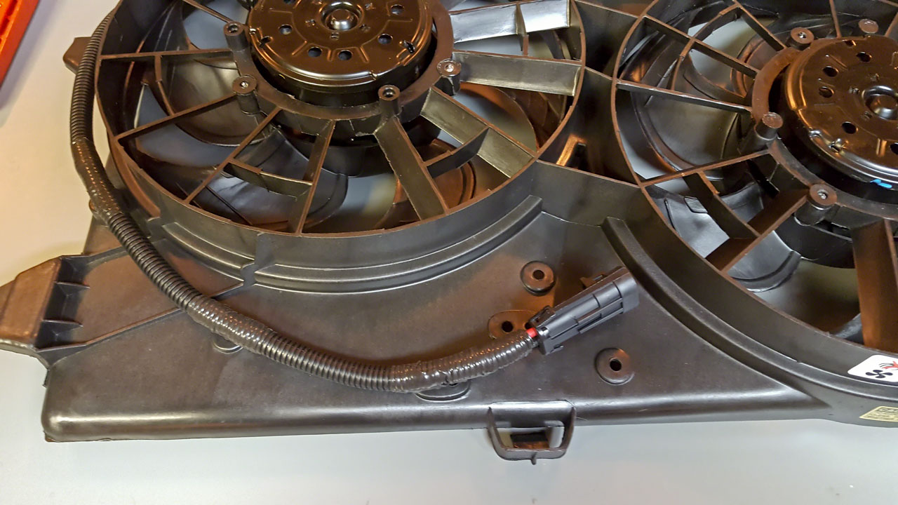
I choose to more or less follow the OEM path. Mostly more. Depending on your vehicle, you might have to work on the driver side fan wire routing a little to clear power steering and/or A/C lines. The original OEM routing runs to the top of the fan shroud but there's no reason why you can't shorten things up and run the controller harness to the bottom of the shroud.
I also always start with the passenger side fan. If you choose to route the connectors to the center top of the shroud, it seems to be easier to finish the passenger side before routing the wiring for the driver side. The driver side loops around the outside edge of the DR fan, back towards the center and then does a 180 degree loop back facing the driver side. If I try to do the driver side first, that all gets in the way and is kinda annoying.
After the splices are completed, I start feeding the wire into the corrugated plastic protector starting at the fan motor plug and continue past where the Metri-Pack connector will go by about 10-12". The wire cover takes up a surprising amount of space and if you run just the wiring to get the length, it will likely be too short once the cover is in place. I start adding rosebuds at the fan motor and work my way around the shroud to where I'm going to locate the Metri-Pack. The location I use for the final rosebuds leaves me with a couple inches which is plenty sufficient to attach the Metri-Pack connectors by just pealing 2" of wire out of the wire protector, crimping on the connector, tucking the wire back in and then dressing the end of the conduit. YMMV here depending on how close the last rosebud is to the Metri-Pack.
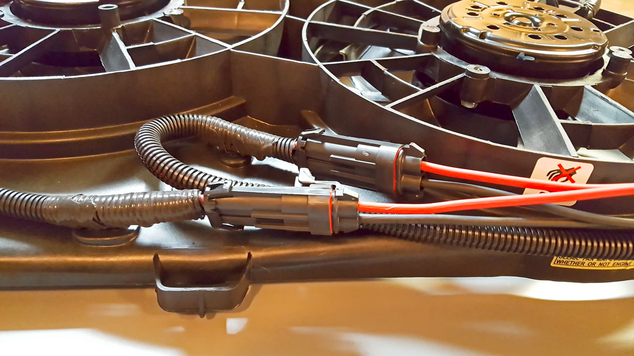
The Delphi Metri-Pack connectors are large and bulky - as large and bulky as the OEM connectors at least. They are, however, a LOT easier to plug and unplug than the OEM or Weather Pack connectors. If you're not familiar with assembling these, there are videos on Youtube which I strongly suggest watching first. Its not difficult but the terminals are a bit on the expensive side to be experimenting with.
I put the large male connectors on the shroud and the female connectors on the controller harness. Functionally it doesn't make any difference, but the male plugs are three times the size of the female ones so I prefer to have those attached to the shroud.
Slide the connector 'weather' seals onto the wire BEFORE crimping, and make sure they're facing the correct direction! Its helpful to do this BEFORE striping on finer stranded wire, but on large heavy wire like I used it didn't cause any issues. Each terminal will require two crimps. The first to attach the wire to the terminal and the second to crimp the weather seal to the terminal. When you have the terminals crimped on, insert the terminals into the connector. Be careful when inserting the terminal. The weather seals are lightly crimped so if you get carried away its possible to unseat the weather seal from the terminal. If that happens, you will need to remove the terminal from the connector and attempt to salvage the terminal or start over with a new terminal.
Something to think about: Both the Painless F5 and Derale fan controllers control both fans simultaneously so unlike the Spal controller setup, there is no difference between the 'left' and 'right' fans. Since I'm using the Derale controller, I make sure that both Multi-Pack connectors on the shroud are wired with positive and negative in the same positions. The most obvious reason is it prevents accidentally reversing the connections and running one fan one direction and the other the opposite direction. Yes, you could 'fix' this issue by running a male on one fan and a female on the other fan, but that makes the other reason for making the connections the same impossible. I like being able to move the connection(s) around.
Strictly speaking, the Metri-Pack connectors are not necessary. It is possible (acceptable) to run directly from the fan motors to the fan controller with no connectors in the middle. Were I to do this I would use the circle clip rosebuds to attach the loom to the fan shroud or its going to be a real PITA to remove from the vehicle and/or service the fan shroud assembly. KIM that if someone else does the timing belt/water pump service (or anything else that requires removal of the fan/radiator assembly) you don't want to make this a big PITA for them, either. If it takes 1/2 an hour to pull and 1/2 hour to install the fan/radiator assembly, they're going to charge you for it. I'd rather spend $10 on connectors once.
Once both sides are wired in, that's it for the fan assembly. I spent a LOT of time screwing around so it took me all weekend, but this shouldn't take more than a couple hours normally.
The next step will be building the other half of the fan harness - the section from the Metri-Pack connectors to the fan controller. Next weekend ....
(I'll post up all the images in the morning)
Edward

Part 1 - Fans
Part 2 - Controller
Derale 16795 PWM Fan Controler Installation
Electric fan contour swap
Part 3 - Installation
I'm not gong to bother with 'part 2' as that's pretty well (recently) documented, but I figured I might as well update parts 1 and 3.
Anyway, part 1 ...

I gave up trying to find an intact Contour fan assembly from the salvage yards, ebay or CL. The vehicles are just too old and too thrashed.
 Instead I bought an entire replacement assembly. Hopefully this one will last for a while as its from Taiwan rather than China.
 Similarly the harnesses are also thrashed.
I had no interest in wasting an entire weekend - again - hunting for the fan motor and assembly connectors - which were really the only pieces I wanted anyway. The last time I did this, it took me longer to rebuild the Ford harness than it would have to build my own but the connectors were not commonly available 5-6 years ago. Now the motor connectors can be sourced from Amazon, eBay, Napa and pretty much every other auto parts supplier I looked at. I settled on the General S827 connector off Amazon. They were cheap and I had 'points'.
The connector looked to be decently made - time will tell. I wasn't happy, however, to find out that the pigtails were 12AWG. I was really hoping for 10AWG, but .... The two OEM connectors at the top of the fan assembly that the main vehicle wiring harness plugs into are brutes. At the time of the building of my first Contour setup, connectors that would handle the amperage of the Contour fan motors were very difficult to source. This time a little searching led me to the Delphi Metri-Pack 480 rated at 42 amps. The terminals are 12-10AWG. The only downside is the requirement of a specific crimper for the larger terminals. My existing Delphi crimper only goes down to 14AWG. You can't 'fake' it - if you don't have the correct crimper you will have issues.
Female connector - 12052613
Female terminal - 12052139-L
Male connector - 12065863
Male terminal - 12052172-L
Secondary lock - 12059897
Weather seals (purple) - 12052453
Hand crimper - 12071687 (12-10 GA Metri-Pack 480 & 630 Series terminals)
(Source: Mouser.com, theElectricalDepot.com)
The last three pieces were heat shielding for the wires, attachment clips and wire.
I had plenty of high temp 10AWG stranded red/black wire so that was easy.
I used thicker strand, stiffer wire for the fan shroud harness. The attachment points on the shroud are a ways apart and I didn't want stuff flopping around and didn't feel like drilling 1/4" holes every 6". The stiffer wire worked out well - but was kind of a PITA to work with.I've run across this problem multiple times, even on OEM harnesses. I settled on using the corrugated plastic split loom wire covering. The stuff you see EVERYWHERE on wiring projects. The problem? The cheap nickle-a-foot multicolored stuff that every auto part and hardware store carries isn't made to go under the hood of a vehicle and it doesn't take long before it starts falling apart and/or melting. Wedging the cheep stuff between the radiator and engine block is not a good plan if you're looking for a long and trouble free installation.
I opted for the black corrugated cover with the grey stripe. There are a couple types of the black tubing and two have a stripe. The blue stripe indicates its flame retardant but the temperature rating is only 200F. The gray strip indicates its high temperature and is rated to 300F. As best as I can tell all black is 200F and some colored protector is also 200F - not high enough for exposure next to an engine.
The black with gray strip isn't hard to find but its hard to identify on the internet sites and most want to sell you 50' or 100' - WAY more than I needed. I love McMASTER-CARR - 5, 25, 50 and 100'. I used 3/8" ID which fit the 10AWG great - except I forgot to take into account the diameter of the splices from the 12AWG connector pig-tails to the 10AWG wire + the double-wall shrink wrap. Sigh. Well, actually I did, I just forgot to stagger my splices.
Without the shrink wrap, everything fit fine - with the shrink wrap the splices barely fit. Mostly. Close enough that I wasn't willing to redo two splices. High-Strength Slit Corrugated Sleeving 3/8"ID
(Source: McMaster-Carr.com)
The last thing was rosebuds to attach the corrugated loom to the fan shroud. Which turned out to be a flaming PITA. I used the standard snap-closed round clips on the last fan build and I didn't like them. The part that snapped into the shroud was too small for the 1/4" hole and no matter what I did - short of installing a bunch more clips - everything flops around.
What I WANTED was the tape on rosebuds.Eventually my search led me back to Mouser and after a little research on their site, I found what I was looking for. These are just like the OEM ones you see on harnesses. Position the rosebud, wrap a couple winds of tape around both ends and snap it in. These are not useful for quick removal of a harness but they're more compact and nicer (IMHO) for a semi-permanent installation. And they don't snag on stuff which was a big plus for me.
Delphi 08911496-B
(Source: Mouser.com)
Misc stuff you need - A GOOD electric (or butane) soldering iron with the appropriate tip. A little 75W from Radio Shack isn't going to cut it when soldering 12AWG to 10AWG, nor is the little needle tip used for fine electronics work. I use a large 'chisel' tip and crank up the temperature.
Also, some good double-walled shrink tube with the adhesive inside. DO NOT just use electrical tape on these splices! These four splices (pos & neg for 2 motors) are going to see a LOT of heat, road crud, water, deicer, vibration and God knows what else over time. The splices need to be permanently sealed.
Rather than regular electrical tape to dress up the loom, I used the high temp self-fusing tape. No glue to break down or melt and become a gooey mess and it doesn't harden up and crack and break. I used the same on my first fan build and that's worked well for a number of years.
Self-Fusing Tape 1" 10yds - 7643A79
(Source: McMaster-Carr.com)
A good wire stripper that will do 8, 10 and 12AWG isn't a necessity but it sure makes the job easier. I have several wire strippers - all of which work good on one or two sizes but suck on the others. Since I have a LOT of wiring to do on this build, I decided to get a really good stripper that would work on everything.
The Klein Katapult Wire Stripper costs about what two of my others cost and so far has worked flawlessly on 10, 12 and 22AWG (silicone and PVC insulation). It does not, however, work on the super fine strand 8AWG from CE. Klein Tools 11063W 8-22 AWG Katapult Wire Stripper
(Source: Amazon.com)
Onwards ...
Because I've long since forgotten, I started by taking one of motor connectors and plugging it in to the fan motor and then connecting the leads to a battery so I could figure out which lead was positive and which was negative.
When looking into the connector on the fan motor, with the shaft (fan blades) pointed down towards the floor, the blade on the right will be pos and the left neg. In the case of my connectors, the positive was the green w/ white stripe.After figuring that out, it was time to splice the connector into the 10AWG wire. Again, unless you're planning on using larger than 3/8"ID wire protector, you will want to stagger the splices.
Splicing together wire this large isn't rocket surgery, but it isn't as easy as two pieces of 18AWG, either. I strip 1" from both ends and do a slightly short Lineman splice. (see pg 71 PDF linked to below) If you want something to practice when you're bored that will come in handy latter, see page 69. NASA TECHNICAL STANDARD - WORKMANSHIP STANDARD FOR CRIMPING, INTERCONNECTING CABLES, HARNESSES, AND WIRING
A tip for those who are new to soldering - DO NOT move the wires while or right after soldering. I do all my work on my workbench with a '3rd set of hands' - which is basically a stand with several flexible arms and alligator clips.
Its almost impossible if you're inexperienced to solder a joint while holding the solder with one hand and the iron with the other if the wires are not held steady, and once you have the joint soldered and you've removed the iron, you DO NOT want to move the joint until the solder has 'set' or cooled down a little.I had several 4-5' 10AWG lengths so I spliced the first motor connector to two 10AWG wires that were significantly longer than I knew I needed so I could tailor the the length. There are lots of preformed 1/4" holes in the shroud and you don't use or need to use all of them.
Its convenient because it lets you route the wires pretty much wherever you might want them. You can solder one splice at a time and shrink wrap or do all the splices and then put all the shrink wrap on. I do one splice at a time for no particular reason.
I have boxes of shrink wrap - all of which takes a different amount of heat to shrink. I use everything from a Bic lighter to butane torch to a 20 year old Conair 1750W hair dryer. This project has reminded me that I spend WAY TOO MUCH time horking around with shrink wrap. Time to get a real heat gun. Too late for this little piece but I have a LOT of heat shrink to go on this build. Master Appliance 10008 650-Degree Fahrenheit 120-volt Master-Mite Heat Shrink System
(Source: Amazon.com)
I choose to more or less follow the OEM path. Mostly more.
Depending on your vehicle, you might have to work on the driver side fan wire routing a little to clear power steering and/or A/C lines. The original OEM routing runs to the top of the fan shroud but there's no reason why you can't shorten things up and run the controller harness to the bottom of the shroud. I also always start with the passenger side fan. If you choose to route the connectors to the center top of the shroud, it seems to be easier to finish the passenger side before routing the wiring for the driver side. The driver side loops around the outside edge of the DR fan, back towards the center and then does a 180 degree loop back facing the driver side. If I try to do the driver side first, that all gets in the way and is kinda annoying.
After the splices are completed, I start feeding the wire into the corrugated plastic protector starting at the fan motor plug and continue past where the Metri-Pack connector will go by about 10-12". The wire cover takes up a surprising amount of space and if you run just the wiring to get the length, it will likely be too short once the cover is in place. I start adding rosebuds at the fan motor and work my way around the shroud to where I'm going to locate the Metri-Pack. The location I use for the final rosebuds leaves me with a couple inches which is plenty sufficient to attach the Metri-Pack connectors by just pealing 2" of wire out of the wire protector, crimping on the connector, tucking the wire back in and then dressing the end of the conduit. YMMV here depending on how close the last rosebud is to the Metri-Pack.
The Delphi Metri-Pack connectors are large and bulky - as large and bulky as the OEM connectors at least. They are, however, a LOT easier to plug and unplug than the OEM or Weather Pack connectors. If you're not familiar with assembling these, there are videos on Youtube which I strongly suggest watching first. Its not difficult but the terminals are a bit on the expensive side to be experimenting with.
I put the large male connectors on the shroud and the female connectors on the controller harness. Functionally it doesn't make any difference, but the male plugs are three times the size of the female ones so I prefer to have those attached to the shroud.
Slide the connector 'weather' seals onto the wire BEFORE crimping, and make sure they're facing the correct direction!
Its helpful to do this BEFORE striping on finer stranded wire, but on large heavy wire like I used it didn't cause any issues. Each terminal will require two crimps. The first to attach the wire to the terminal and the second to crimp the weather seal to the terminal. When you have the terminals crimped on, insert the terminals into the connector. Be careful when inserting the terminal. The weather seals are lightly crimped so if you get carried away its possible to unseat the weather seal from the terminal. If that happens, you will need to remove the terminal from the connector and attempt to salvage the terminal or start over with a new terminal. Something to think about: Both the Painless F5 and Derale fan controllers control both fans simultaneously so unlike the Spal controller setup, there is no difference between the 'left' and 'right' fans. Since I'm using the Derale controller, I make sure that both Multi-Pack connectors on the shroud are wired with positive and negative in the same positions. The most obvious reason is it prevents accidentally reversing the connections and running one fan one direction and the other the opposite direction. Yes, you could 'fix' this issue by running a male on one fan and a female on the other fan, but that makes the other reason for making the connections the same impossible. I like being able to move the connection(s) around.
Strictly speaking, the Metri-Pack connectors are not necessary. It is possible (acceptable) to run directly from the fan motors to the fan controller with no connectors in the middle. Were I to do this I would use the circle clip rosebuds to attach the loom to the fan shroud or its going to be a real PITA to remove from the vehicle and/or service the fan shroud assembly. KIM that if someone else does the timing belt/water pump service (or anything else that requires removal of the fan/radiator assembly) you don't want to make this a big PITA for them, either. If it takes 1/2 an hour to pull and 1/2 hour to install the fan/radiator assembly, they're going to charge you for it. I'd rather spend $10 on connectors once.
Once both sides are wired in, that's it for the fan assembly. I spent a LOT of time screwing around so it took me all weekend, but this shouldn't take more than a couple hours normally.
The next step will be building the other half of the fan harness - the section from the Metri-Pack connectors to the fan controller. Next weekend ....
(I'll post up all the images in the morning)
Edward